Page 26
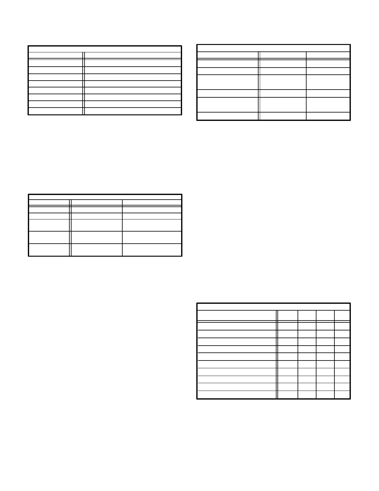
TABLE 7
COMPRESSOR START CAPACITOR
Unit MFD @ Volts
GCS16H-261
GCS16H-311
GCS16-411
GCS16-511
GCS16R-651
Not Used
Not Used
Not Used
176 to 216 @ 320 VAC
135 to 155 @ 320 VAC
GCS16R-411 Not Used
GCS16R-511 135 to 155 @ 320 VAC
GCS16-651
176 to 216 @ 320 VAC
5-Compressor Run Capacitor C5
All singlephase units use compressor run capacitors to
maximize compressor efficiency. Table 8 shows run ca
pacitors used in GCS16 singlephase units. Threephase
units do not use run capacitors. See figure 3 for capacitor
location.
TABLE 8
COMPRESSOR RUN CAPACITOR
Unit MFD @ Volts
GCS16H-261
GCS16H-311
GCS16-411
GCS16R-411
GCS16R-511
GCS16-511
GCS16R-651
GCS16-651
Type
Single
Single
Dual (shared with
condenser fan)
Single
Single
30 @ 370
35 @ 370
40 @ 370
40 @ 440
45 @ 440
6-Condenser Coil
All GCS16s have a single condenser coil. Each coil has
two rows (GCS16-511/513 and GCS16R-511 have 1-1/2
rows) of copper tubes fitted with rippleedged aluminum
enhanced fins.
7-Condenser Fan and Motor B4
The specifications table on page 1 in this manual shows
the specifications of condenser fans used in GCS16s.
The condenser fan in all units is controlled by cooling con
tactor K1.
8-Condenser Fan Motor Capacitor C1
All GCS16s use singlephase PSC condenser fan motors.
Table 9 shows fan run capacitor ratings for GCS16s.
TABLE 9
CONDENSER FAN MOTOR CAPACITOR
Unit & Unit Voltage
GCS16H-261 7 370
GCS16H-311
Type MFD @ Volts
Single
Single
GCS16-411
GCS16R-411
Dual (shared with
compressor)
7 370
5 370
GCS16-413 Single 5 370
208/230
208/230
208/230
ALL
GCS16-511/651
GCS16R-511/651
208/230
Single 7 370
GCS16-513/653 ALL Single 7 370
9-Blower Motor B3
All GCS16 series units use singlephase PSC blower mo
tors. A single run capacitor is mounted on the blower hous
ing. All motors use multiple speed taps. Typically, the high
speed tap is energized during compressor operation and a
lower speed tap is energized during heating operation.
Blower motors in GCS16 -261, -311 and -411 units have
four speed taps. Motors in GCS16 -511 and -651 units
have five speed taps. All G (460V) and J (575V) voltage
units have three taps. Blower motor specifications are
listed in table 10. Blower specifications are listed in the
tables on pages 1 and 2.
A third (blue) tap on G (460V) and J (575V) volt motors is
used to complete an internal circuit during low or medium
speed operation. It must never be connected to line volt
age. During low speed (red tap) operation, the high speed
(black) tap is disconnected from line voltage and is con
nected to blue internal wiring tap (see figure 24). Internal
wiring is shown in figure 25.
TABLE 10
BLOWER MOTOR - 825 RPM - CCW ROTATION
Unit
Volts
Phase HP FLA
GCS16H-261
GCS16H-311
GCS16-411/413 GCS16R-411
GCS16-511/513 GCS16R-511
GCS16-513
GCS16-651/653 GCS16R-651
GCS16-653
208/230
208/230
208/230
208/230
208/230
460
460
1
1
1
1
1
1
1
1/3
1/3
1/2
3/4
3/4
3/4
3/4
2.2
2.2
3.9
4.6
1.8
4.6
1.8
Motor
575
GCS16-413 460 1 1/2 1.8
GCS16-513 575 1 3/4 0.7
GCS16-653 1 3/4 0.7
 Loading...