Page 27
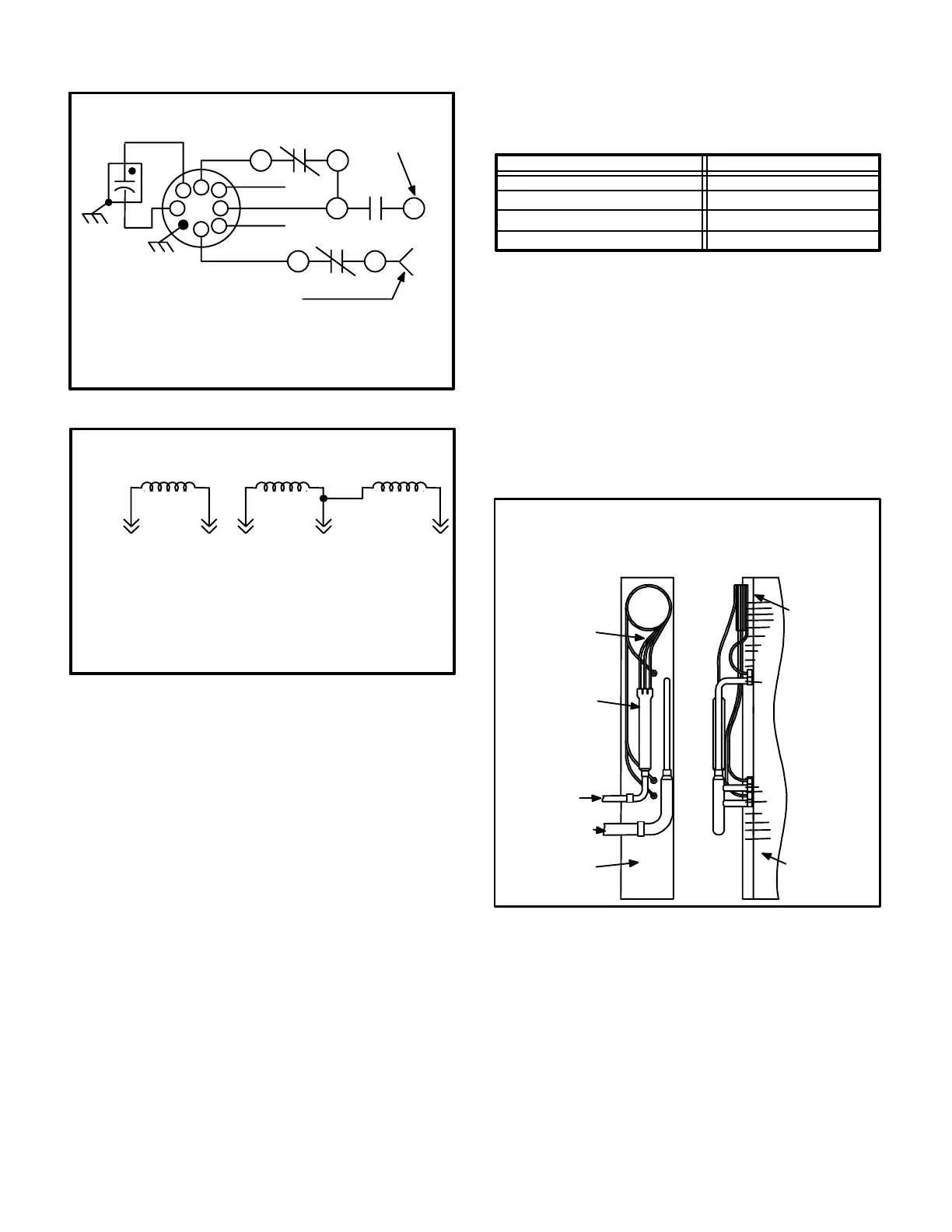
FIGURE 24
BR2
BR2
BR1
RED-LOW
BLUE
BLACK-HIGH
P9
TO COMPRESSOR
DEMAND
TO ELECTRIC
HEAT DEMAND
G VOLTAGE BLOWER MOTOR
TYPICAL
NOTE - The blue tap on G voltage motors is not a speed tap. It is
used with the blower relay during low and medium speed opera
tion to complete an internal circuit. DO NOT CONNECT THE
BLUE TAP TO LINE VOLTAGE.
YELLOW
ORANGE
FIGURE 25
ORANGE BLACK BLUE YELLOW RED
WINDING WINDING WINDING
HIGH SPEED MEDIUM SPEED LOW SPEED
460 VOLT BLOWER MOTOR WINDINGS
The motor has three sets of windings. The high speed winding is
independent of the other two and the medium and low speed wind
ings are tied together with a center tap. High speed is accomplished
by energizing the high speed windings. Medium speed is accom
plished by connecting the medium speed and high speed windings
in series. Low speed is accomplished by connecting the low, me
dium and high speed windings in series. Refer to unit wiring diagram
and Corp. 8909-L7.
WARNING - DO NOT ISOLATE MEDIUM OR LOW
SPEED WINDINGS WHEN OPERATING AT ME
DIUM OR LOW SPEED. THE BLUE LEAD MUST
NEVER BE CONNECTED TO A POWER LEAD
(BLOWER DEMAND FROM HEAT RELAY OR
BLOWER RELAY) OR TO COMMON. FAILURE TO
CONNECT THE BLUE TAP AS SHOWN ON UNIT
DIAGRAM WILL CAUSE IMPROPER OPERATION,
INCREASED CURRENT FLOW AND/OR BURNT
WINDINGS.
10-Indoor Blower Motor Capacitor C4
All GCS16 208/230v units use singlephase PSC motors.
The run capacitor is mounted on the blower housing. Ca
pacitor ratings are shown in table 11.
460v and 575v units use threephase 460v blower motors.
Run capacitor is not required.
TABLE 11
Unit 208/230v Blower Capacitor Rating
GCS16H-261/-311
GCS16-411/-413 GCS16R-411
GCS16-511-/-513 GCS16R-411
7 MFD at 370 V
10 MFD at 370 V
20 MFD at 370 V
GCS16-651-/-653 GCS16R-411 20 MFD at 370 V
11-Evaporator Coil
All GCS16s have a single slab evaporator coil. The coil
has two rows of rifled copper tubes fitted with rippleedged
aluminum fins. An expansion device feeds multiple paral
lel circuits through the coil.
a-Capillary Tubes
GCS16H-261, GCS16H-311, GCS16-411/413 and
GCS16R-411 units use capillary tubes as the primary
expansion device. Each tube feeds an independent
parallel circuit through the coil. See figure 26.
FIGURE 26
END VIEW SIDE VIEW
EVAPORATOR PLUMBING
GCS16H-261, GCS16H-311,
GCS16-411/413 and GCS16R-411
LIQUID LINE
SUCTION LINE
CAP TUBES
DISTRIBUTOR
EVAPORATOR
EVAPORATOR
CAP TUBES
b-Expansion Valve
GCS16 -510 through -650 series units use a Thermal
Expansion Valve (TXV) as the primary expansion de
vice. See figure 27.
 Loading...