Page 35
diately in the event of a gas or power failure. Upon restora
tion of gas and power, the control will restart the ignition
sequence and continue until flame is established or sys
tem lockout occurs.
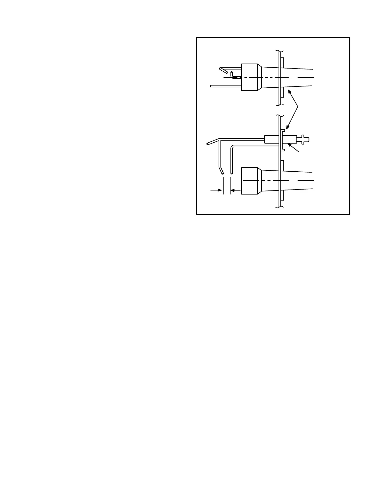
For proper unit operation, the electrodes must be positioned
correctly in the flame and must be gapped correctly.
DANGER - SHOCK HAZARD. SPARK RELATED
COMPONENTS CONTAIN HIGH VOLTAGE. DIS
CONNECT POWER BEFORE SERVICING.
WARNING - THE IGNITION CONTROL IS NOT
FIELD REPAIRABLE. UNSAFE OPERATION WILL
RESULT.
M-Spark Electrode/Flame Sensor/Spark
Gap
DANGER - SHOCK HAZARD. SPARK RELATED
COMPONENTS CONTAIN HIGH VOLTAGE. DIS
CONNECT POWER BEFORE SERVICING.
The electrode assembly can be removed for inspection by
removing two screws securing the electrode assembly
and sliding it out of unit.
Spark gap may be checked with appropriately sized twist
drills or feeler gauges. Disconnect power to the unit and
remove electrode assembly. The gap should be between
0.094" and 0.156". See figure 35.
DANGER - ELECTRODES ARE NOT FIELD AD
JUSTABLE. ANY ALTERATIONS TO THE ELEC
TRODE MAY CREATE A HAZARDOUS CONDITION
THAT CAN CAUSE PROPERTY DAMAGE OR PER
SONAL INJURY.
N-Flame Sensing
Flame current is an electrical current which passes from
the ignition control through the sensor electrode during
unit operation. The current passes from the sensor
through the flame to ground electrode to complete a safety
circuit. The minimum flame current necessary to keep the
ignitor from lockout is 5 microamps. The electrodes should
be located so the tips are at least 1/2" inside the flame en
velope. Do not bend electrodes. To measure flame cur
rent, follow the procedure below:
1-Disconnect power to unit.
2-Remove lead from sensing electrode and install a
0-50DC microamp meter in series between the
sensing electrode and the sensing lead.
3-Reconnect power and adjust thermostat for heating
demand.
4-When flame is established, meter reading should
be 8 to 20 microamps. Do not bend electrodes.
FIGURE 35
C
L
C
L
GCS16 BURNER / ELECTRODE ASSEMBLY
BURNER
ASSEMBLY
TOP VIEW
SIDE VIEW
IGNITION
ELECTRODE
.094" TO .156"
GAP
5-When finished, disconnect power to unit before dis
connecting meter. Make sure sensor wire is se
curely reconnected before reconnecting power to
unit.
NOTE - If the meter scale reads 0, the leads are re
versed. Disconnect power and reconnect leads for
proper polarity.
O-Combustion Air Blower B6
The combustion air blower, prove switch, connecting hose
and orifice are factory set and are not field adjustable.
However, operation should be monitored to ensure proper
operation. The combustion air blower is used to draw fresh
air into the combustion chamber while simultaneously ex
pelling exhaust gases. The blower operates throughout
the heating cycle. On a heating demand, the combustion
air blower immediately energizes but the ignition control
circuit does not. Once the combustion air blower is ener
gized and moving air through the heat exchanger, the
combustion air prove switch closes to energize the ignition
control. The ignition control then begins attempting igni
tion after 30-40 seconds.
If the combustion air blower does not reach full speed or if
the hose connecting the blower to the prove switch is ob
structed, the prove switch will not close and the ignition
control will not energize.
 Loading...