Page 40
IMPORTANT - Pay close attention to the order in
which the flue orifice and gaskets are installed.
Inspect all gaskets for deterioration. Replace if neces
sary.
3- Remove the screws holding the blower housing to the
flue box cover plate and wires attached to the motor.
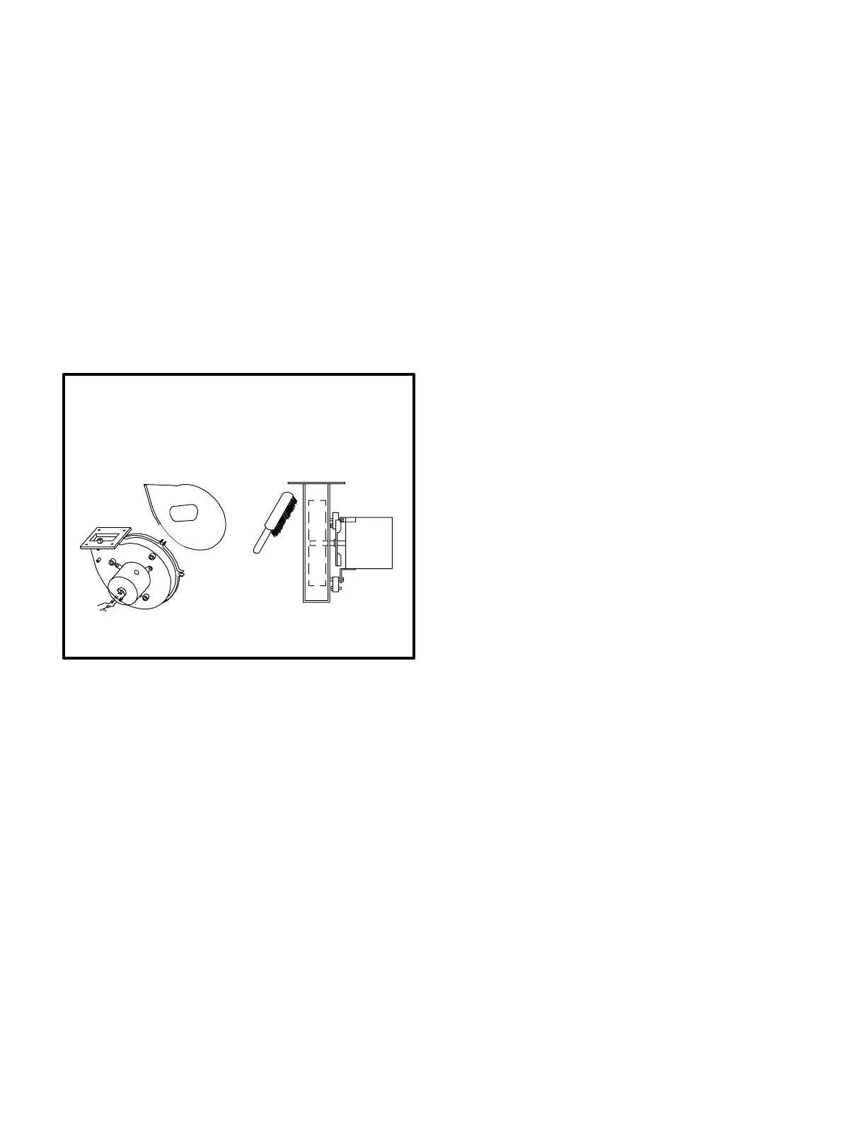
4- If blower can be disassembled (50,000, 75,000, and
100,000 Btuh heat exchangers only), remove blower
backplate as shown in figure 39. Clean blower blades
with a small brush and wipe off any dust from the
housing (see figure 39). Clean any accumulated dust
from inside the flue box cover.
If blower cannot be disassembled (125,000 Btuh heat
exchanger only), clean off any accumulated dust and
reassemble.
FIGURE 39
COMBUSTION AIR BLOWER DISASSEMBLY
CLEAN BLOWER
WHEEL WITH BRUSH.
50, 75, 100 K Btuh UNITS ONLY
REMOVE BLOWER
BACKPLATE
SEAL BACKPLATE WITH HIGH TEMPERATURE
RTV SEALANT WHEN REASSEMBLING
CAUTION - USE CARE WHEN CLEANING COM
BUSTION AIR BLOWER WHEEL. WHEEL IS MADE
OF ALUMINUM AND MAY DISTORT IF TOO MUCH
PRESSURE IS APPLIED.
5- Reassemble combustion air blower by reversing this
procedure. Seal backplate with high temperature RTV
sealant when reassembling.
6- Reconnect tubing connecting blower to flue box. Ar
range tubing so that it can drain accumulated conden
sate.
7- Clean the vestibule panel louvers using a small brush.
F-Flue
Make sure the flue is clean and free of debris.
G-Evaporator Coil
1- Clean coil, if necessary.
2- Check connecting lines and coil for evidence of oil
leaks.
3- Check condensate drain pan and line, if necessary.
H-Condenser Coil
1- Clean and inspect condenser coil. (May be flushed
with a water hose.)
2- Visually inspect connecting lines and coils for evi
dence of oil leaks.
NOTE - If owner complains of insufficient cooling, the unit
should be gauged and refrigerant charge checked. Refer
to Gauge Manifold Attachment, Checking Charge and
Charging sections in this instruction.
I-Electrical
1- Check all wiring for loose connections.
2- Check for correct voltage at unit (unit operating).
3- Check ampdraw on both condenser fan motor and
blower motor.
Fan Motor Rating Plate ____ Actual ________
Indoor Blower Motor Rating Plate____ Actual____
X-ELECTRICAL CONNECTIONS
A-Power Supply
Refer to start up directions and refer closely to the unit wir
ing diagram when servicing. Refer to the unit nameplate
for minimum circuit ampacity and maximum fuse size.
208/460/575 volt units are wired with a red wire connecting
transformer T1 primary to L1. 230 volt units use an orange
wire connecting transformer T1 primary to L1.
B-Field Wiring
Unit and optional control field wiring is shown in the unit
diagram section of this manual.
 Loading...