Page 59
a-The COOL MODE" LED lights green to indicate
economizer free cooling" operation when unit in
cludes the economizer option. Otherwise, the LED
indicates mechanical cooling operation.
b-The HEAT MODE" LED lights green during normal
heating operation.
c-The COMPRESSOR 1" LED lights green when the
compressor is running. The light turns red if a com
pressor safety switch opens during a compressor
demand (singlephase units must be equipped with
optional Controls Package for the red function of
this LED to operate).
d-The COMPRESSOR 2" LED is not used in GCS16
210 through 650 series units.
e-The NO HEAT" LED lights red on a loss of heat dur
ing a heating demand.
f- The FILTER" LED lights red when optional filter
pressure switch contacts close indicating a dirty fil
ter.
g-The SYSTEM" switch on the SSP11 has five posi
tions to indicate the following functions:
OFF" - System off.
HEAT" - System operates in heating mode only.
AUTO" - System automatically provides heating or
cooling on demand.
COOL" - System operates in cooling mode only.
EM HEAT" - (Emergency Heat) Not used in
GCS16 units, but if placed in this position, the unit
operates in the normal heating only mode.
h-The FAN" switch on the SSP11 has two positions to
indicate the following functions:
AUTO" - Blower cycles with demand.
ON" - Blower runs continuously.
i- The AFTER HOURS TIMER" on the SSP11 pro
vides override of unoccupied mode operation (night
heating setback / cooling setup) from 0 to 12 hours.
In the occupied (day) mode, the after hours timer
has no effect on unit operation.
The unit must be in the unoccupied mode (night) to
activate the timer. Set the potentiometer for the
number of hours desired override and push the mo
mentary start button. The unit reverts to occupied
mode operation for the set number of hours.
4-Installation and Wiring
The SP11 and SSP11 require relay kits to interface the
status panel to the control system and the unit. The fol
lowing sections list the operation sequence and instal
lation procedures for the relay kits and the status pan
els.
a-Readout Relay Kit
A readout relay kit (readout relay box - RRB) is re
quired for all units using either the SP11 or SSP11
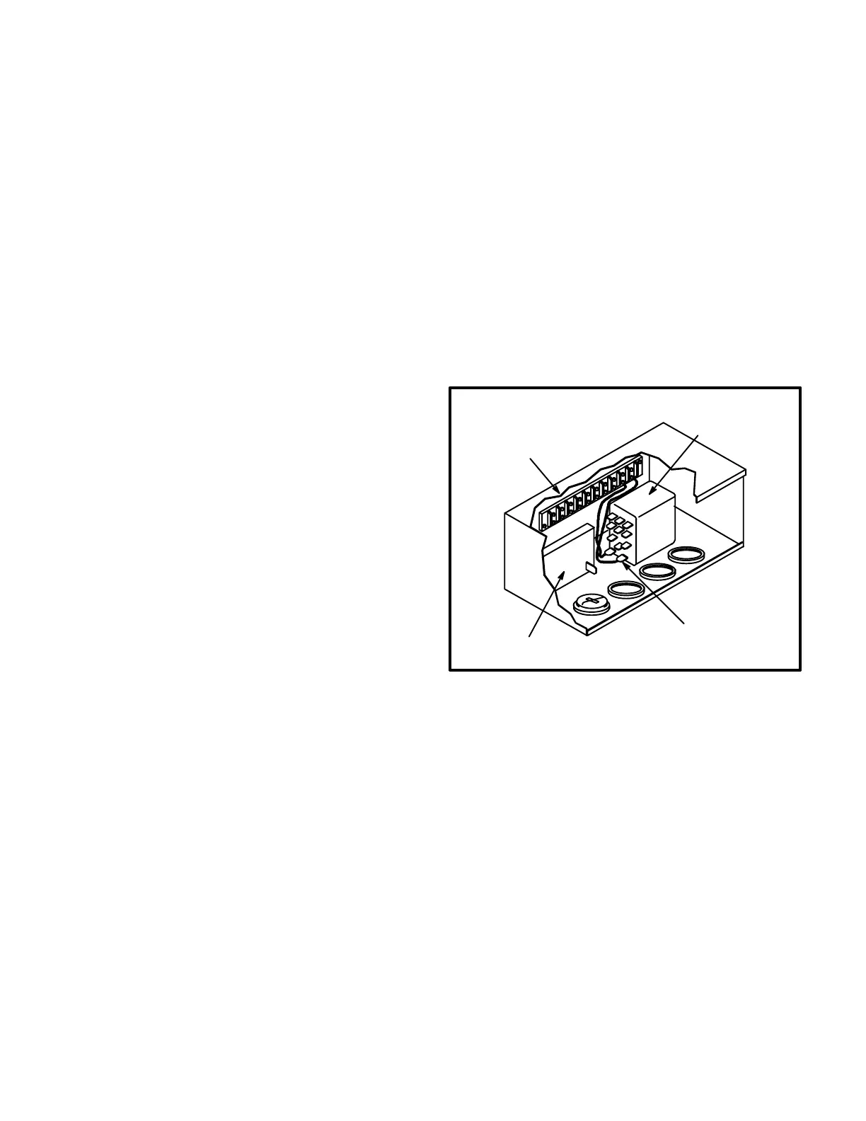
status panels. RRB is shown in figure 78. The RRB
includes relays which interface the status panels to
the unit. The status panels will not operate without
the RRB.
FIGURE 78
READOUT RELAY BOX
RELAY K29
TERMINAL STRIP
TIME DELAY DL6
CONNECT RELAY COIL TERMI
NALS C AND C TO TERMINAL
STRIP TERMINALS 9 AND 10.
RRB Sequence of Operation:
1- Initial heating demand (W1) from the unit is
routed through RRB terminal 2 to SP11 terminal
2 to light the green HEAT" light.
2- The same heat demand is routed through RRB
terminal 2 and through (RRB relay) K29 N.C.
contacts to energize time delay DL6.
3- Time delay DL6 begins a 60second count before
closing.
 Loading...