Page 11
OPERATING SEQUENCE
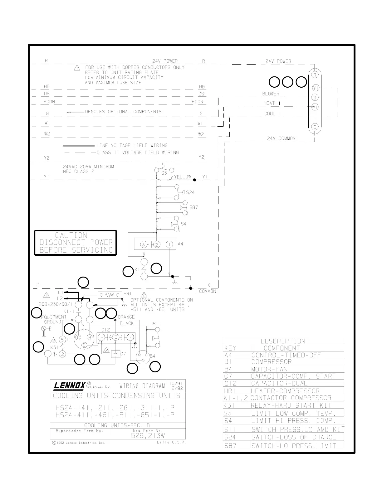
A-HS24 (P Voltage) Operation Sequence
This is the sequence of operation for HS24 P voltage
units. The sequence is outlined by numbered steps
which correspond to circled numbers on the adjacent
diagram.
NOTE-The thermostat used may be electromechaniĆ
cal or electronic.
CoolingĆNo Start Components:
1- Cooling demand initiates at Y1 in the thermostat.
2- Compressor contactor K1 is energized
3- K1-1 N.O. closes energizing terminal C" of compresĆ
sor (B1) and condenser fan motor (B4).
4- Compressor (B1) and condenser fan motor (B4) begin
immediate operation.
End of Cooling Demand:
5- Cooling demand is satisfied.
6- Contactor K1 is deĆenergized.
7- K1-1 opens. and compressor (B1) and condenser fan
motor (B4) are deĆenergized and stop immediately.
CoolingĆWith Start Components:
8- Cooling demand initiates at Y1 in the thermostat.
9- Compressor contactor K1 is energized
10-K1-1 N.O. closes energizing terminal C" of compresĆ
sor (B1) and condenser fan motor (B4).
11-Terminal R is powered by L2 through the contactor. It is
powered at all times. Terminal S is powered by the
start capacitor and the H side of the dual capacitor.
12-As the compressor nears full speed, the potential
relay is energized (terminals 5Ć2) and potential relay
contacts 1Ć2 open.
XII–WIRING DIAGRAMS AND SEQUENCE OF OPERATION
1
2
3
4
6
7
4
5
7
7
S1
THERMOSTAT
SINGLE PHASE OPERATING SEQUENCE
8
9
10
11
12
 Loading...