Page 51
C2 diagram
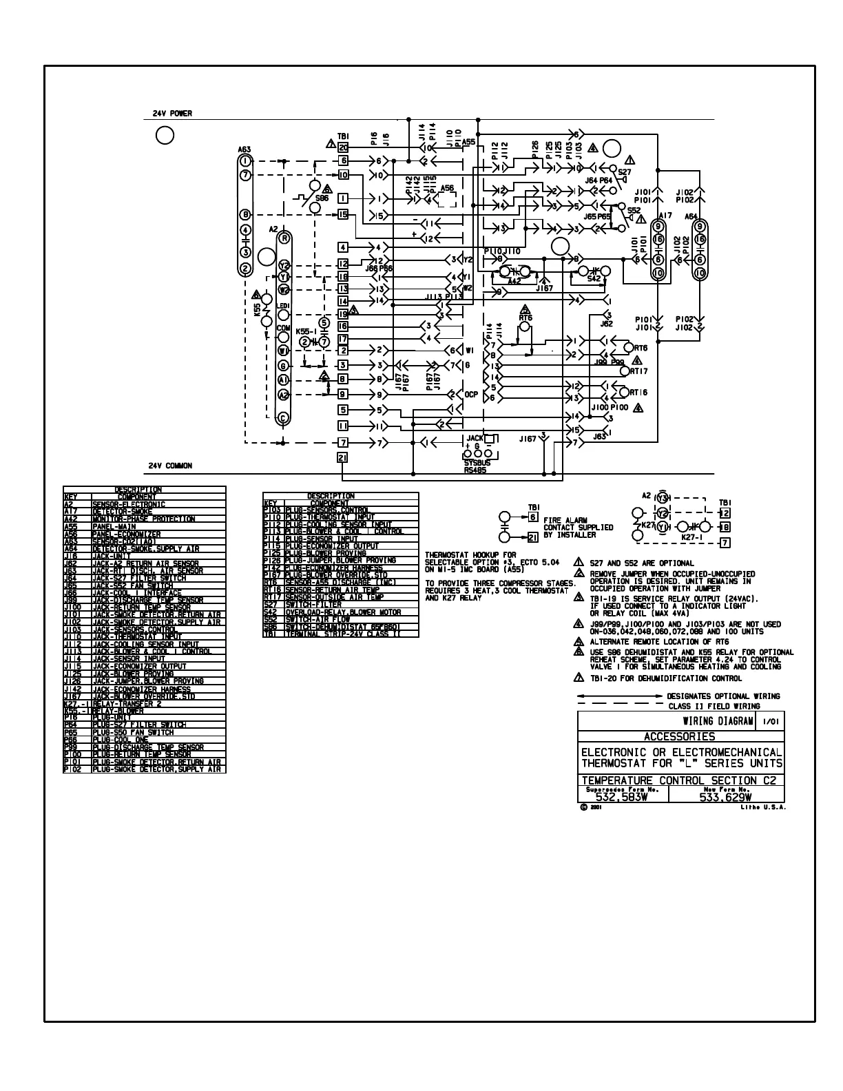
ELECTRONIC OR ELECTROMECHANICAL THERMOSTAT
1
2
4
SEQUENCE OF OPERATION
C2 DIAGRAM - ELECTRONIC OR ELECTROMECHANICAL THERMOSTAT
POWER:
1. Terminal strip TB34 energizes the thermostat components with 24VAC via TB1.
OPERATION:
2. The main control module A55 proves the optional N.O. filter switch S27(indicates dirty filter when closed), optional N.O. airflow
switch S52(indicates no air [i.e. broken belt] system shuts down), and optional C.G.A. -50° C low ambient kit thermostat S59
(used in C.G.A. units only).
3. The main control module A55 receives data from the supply and return smoke detectors A17 and A64,
optional phase protection monitor A42, blower motor overload relay S42, discharge sensor RT6, return air sensor RT16, and
the outdoor air sensor RT17.
4. The main control module A55 receives data from the electronic thermostat A2 (Y1, Y2, W1, W2, G, OCP)
and the CO
2
sensor (if economizer is used) via terminal strip TB1. A55 energizes the appropriate components.
3
 Loading...


