Page 68
LGH/LCH036, 048, 060, 072, 074
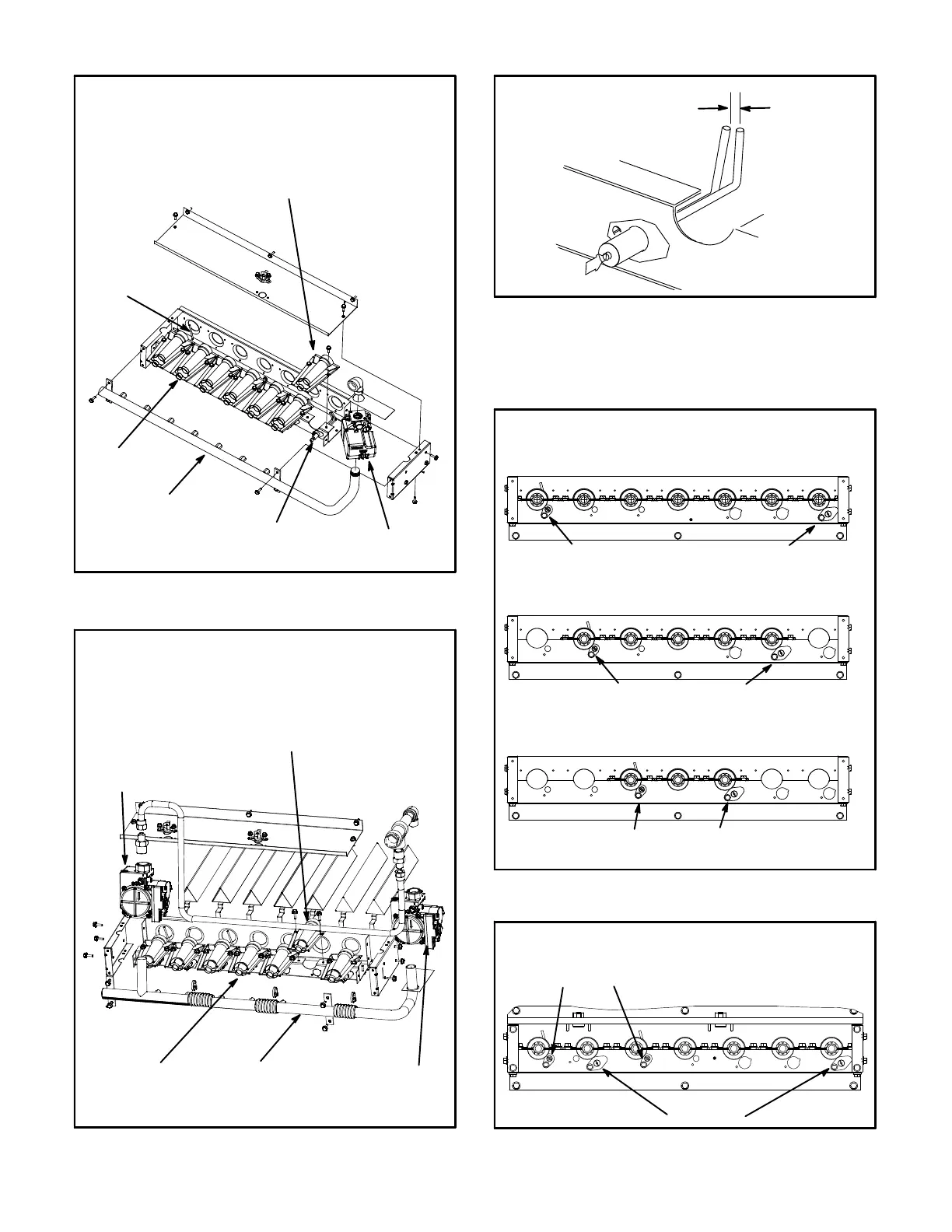
FIGURE 31
BURNER BOX ASSEMBLY
Single- and Two-Stage
GAS VALVE
GAS MANIFOLD
FLAME
SENSOR
BURNERS
IGNITOR
REMOVE INDIVIDUAL BURNERS ON
OLDER UNITS; REMOVE THE ENTIRE
BURNER ASSEMBLY ON NEWER UNITS.
FIGURE 32
BURNER BOX ASSEMBLY
Four-Stage
GAS VALVE
GV3
GAS
MANIFOLD
BURNERS
GAS VALVE
GV1
REMOVE INDIVIDUAL BURNERS ON
OLDER UNITS; REMOVE THE ENTIRE
BURNER ASSEMBLY ON NEWER UNITS.
FIGURE 33
IGNITOR
SPARK GAP
SHOULD BE 1/8”
(3mm)
8- Restore electrical power and gas supply. Follow
lighting instructions attached to unit and use
inspection port in access panel to check flame.
FIGURE 34
BURNER ORIENTATION
One- and Two-Stage Heat
150,000 BTUH - 7 BURNERS
108,000 BTUH - 5 BURNERS
65,000 BTUH - 3 BURNERS
SENSOR IGNITOR
SENSOR IGNITOR
SENSOR IGNITOR
FIGURE 35
BURNER ORIENTATION
Four-Stage Heat
SENSORS
IGNITORS
 Loading...


