LF24 − 100,000 to 400,000 Btuh / Page 5
HIGH ALTITUDE DERATE
Unit may be fired at full input up to 2000 feet above sea level. Above 2000 feet, manifold pressure must be adjusted on
some units. Adjust pressure regulator to pressure shown in tables. If unit is installed at an altitude greater than 7500 ft.
unit must be derated by 4 percent for each additional 1000 ft. above 7500 ft. In Canada, certification for installation at alti-
tudes over 4500 feet above sea level is the jurisdiction of the local authorities.
NOTE − This is the only permissible derate for the units.
Model
No.
Natural Gas Manifold Pressure − in. w.c.
0−2000 ft. 2000−2500 ft. 2500−3500 ft. 3500−4500 ft. 4500−5500 ft. 5500−6500 ft. 6500−7500 ft.
LF24−100
LF24−115
LF24−300
No
adjustment
No
adjustment
No
adjustment
No
adjustment
3.4 3.3 3.2
LF24−145
No
adjustment
3.4 3.3 3.2 3.1 3.0 2.9
LF24−175
LF24−230
No
adjustment
No
adjustment
1
No
adjustment
1
No
adjustment
1
No
adjustment
1
No
adjustment
1
No
adjustment
LF24−200
LF24−250
LF24−345
LF24−400
No
adjustment
No
adjustment
No
adjustment
3.4 3.3 3.2 3.1
1
LF24−175 Combustion air inducer pressure switch must be replaced at altitudes from 2500−7500 ft. Order 10K73 pressure switch.
Model
No.
LPG/Propane Manifold Pressure − in. w.c.
0−2000 ft. 2000−2500 ft. 2500−3500 ft. 3500−4500 ft. 4500−5500 ft. 5500−6500 ft. 6500−7500 ft.
LF24−100
LF24−115
LF24−300
No
adjustment
No
adjustment
No
adjustment
No
adjustment
8.7 8.4 8.1
LF24−145
No
adjustment
8.7 8.4 8.1 7.8 7.5 7.2
LF24−175
LF24−230
No
adjustment
No
adjustment
1
No
adjustment
1
No
adjustment
1
No
adjustment
1
No
adjustment
1
No
adjustment
LF24−200
LF24−250
LF24−345
LF24−400
No
adjustment
No
adjustment
No
adjustment
9.2 8.9 8.6 8.3
1
LF24−175 Combustion air inducer pressure switch must be replaced at altitudes from 2500−7500 ft. Order 10K73 pressure switch.
THROW DATA
Model No.
Air Volume
1
Effective Throw
cfm feet
LF24−100, LF24−115,
LF24−145
1900 60
LF24−175, LF24−200 2200 65
LF24−230, LF24−250,
LF24−300, LF24−345,
LF24−400
4400 80
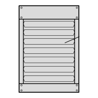
NOTE − Adjustable horizontal louvers on unit allow a variation in throw and spread.
1
Throw terminates where velocity reaches 50 ft.per minute.
1
RECOMMENDED MOUNTING HEIGHT
Model No. Feet
LF24−100, LF24−115 16
LF24−145, LF24−175,
LF24−200
20
LF24−230, LF24−250,
LF24−300, LF24−345,
LF24−400
30
1
Recommended maximum mounting height from floor to bottom of unit. At heights
greater than shown air throw distance and air temperature at floor level is affected.
INSTALLATION cLEARANCES
Top 6 inches
Sides 6 inches
Rear 18 inches
Bottom 0 inches
Flue 6 inches
NOTE − Provide adequate clearance for servicing.
See Installation Instructions for further installation considerations.
MAXIMUM HORIZONTAL VENT LENGTHS
No. of
Elbows
LF24−100
−115−145
−175−200
LF24−230
−250
−300
LF24−345 LF24−400
1 25 35 31 21
2 20 30 22 12
3 15 25 13 3
4 10 20 4 − − −
5 5 15 − − − − − −
6 − − − 10 − − − − − −
7 − − − 5 − − − − − −