Page 31
LGM/LCM036, 048, 060, 074
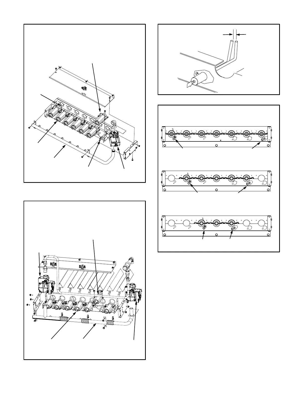
FIGURE 28
BURNER BOX ASSEMBLY
Single- and Two-Stage
GAS VALVE
GAS MANIFOLD
FLAME
SENSOR
BURNERS
IGNITOR
REMOVE INDIVIDUAL BURNERS ON
OLDER UNITS; REMOVE THE ENTIRE
BURNER ASSEMBLY ON NEWER UNITS.
FIGURE 29
BURNER BOX ASSEMBLY
Four-Stage
GAS VALVE
GV3
GAS
MANIFOLD
BURNERS
GAS VALVE
GV1
REMOVE INDIVIDUAL BURNERS ON
OLDER UNITS; REMOVE THE ENTIRE
BURNER ASSEMBLY ON NEWER UNITS.
FIGURE 30
IGNITOR
SPARK GAP
SHOULD BE 1/8”
(3mm)
FIGURE 31
BURNER ORIENTATION
One- and Two-Stage Heat
150,000 BTUH - 7 BURNERS
108,000 BTUH - 5 BURNERS
65,000 BTUH - 3 BURNERS
SENSOR IGNITOR
SENSOR IGNITOR
SENSOR IGNITOR
D-Combustion Air Inducer (Gas Units)
A combustion air proving switch checks combustion air
inducer operation before allowing power to the gas
controller. Gas controller will not operate if inducer is
obstructed.
Under normal operating conditions, the combustion air
inducer wheel should be checked and cleaned prior to the
heating season. However, it should be examined
periodically during the heating season to establish an
ideal cleaning schedule.
Clean combustion air inducer as follows:
1- Shut off power supply and gas to unit.
2- Remove the mullion on the right side of the heat
section.
3- Disconnect pressure switch air tubing from
combustion air inducer port.
 Loading...