EasyManua.ls Logo

Lennox LGM180 User Manual

Lennox LGM180
65 pages
To Next Page IconTo Next Page
Page #1 background imageLoading...
Page #1 background image
Page 1
UNIT INFORMATIONUNIT INFORMATION
Service Literature
WARNING
Improper installation, adjustment, alteration, service
or maintenance can cause property damage, personal
injury or loss of life. Installation and service must be
performed by a licensed professional HVAC installer or
equivalent, service agency, or the gas supplier.
WARNING
Electric shock hazard. Can cause injury or
death. Before attempting to perform any
service or maintenance, turn the electrical
power to unit OFF at disconnect switch(es).
Unit may have multiple power supplies.
Table of Contents
Options / Accessories . . . . . . . . . . . . . . . . . . .Page 2


Blower Data . . . . . . . . . . . . . . . . . . . . . . . . . . . Page 10
Electrical Data . . . . . . . . . . . . . . . . . . . . . . . . . Page 13


II-Placement and Installation . . . . . . . . . . . . . . .Page 33
III-Charging . . . . . . . . . . . . . . . . . . . . . . . . . . . . Page 33
IV-Start Up - Operation . . . . . . . . . . . . . . . . . . . Page 35
V-System Service Checks . . . . . . . . . . . . . . . . .Page 37

VII-Accessories . . . . . . . . . . . . . . . . . . . . . . . . .Page 40
VIII-Hot Gas Re-Heat . . . . . . . . . . . . . . . . . . . . Page 44
IX-Staged Blower . . . . . . . . . . . . . . . . . . . . . . . Page 48
X - VAV System . . . . . . . . . . . . . . . . . . . . . . . . .Page 50
XI-Wiring and Operation Sequence . . . . . . . .Page 52
-
ure to order units (CTO) with a wide selection of factory
installed options.
         
Btuh. See SPECIFICATIONS-GAS HEAT for more detail
per model.
Gas heat sections are designed with aluminized steel tube
heat exchangers with stainless steel as an option.
Cooling capacities range from 13 to 25 tons (45.7 to 88
kW).
-
denser fans, while LGM210, 240 and 300 utilize four com-
pressors and six condenser fans.
Multi-Stage Air Volume MSAV® blower option is available.
The VFD-driven blower will operate at lower speeds when
demand is low and increase to higher speeds when de-
mand is high.
Variable speed VAV system is available as an option which
enables supply duct static measurement to control blow-
er CFM and discharge air temperature to control cooling
stages.
󰀨-
ent energy management thermostat control systems with
-
tions connect to the unit through Smartwire connectors.
When “plugged in” the controls become an integral part of
the unit wiring.
The CORE Control System is designed to accelerate
equipment install and service. Standard with all Model L™
rooftop units, control system integrates key technologies
 󰀩 
protect your investments.
The CORE Unit Controller is a microprocessor-based con-

Information contained in this manual is intended for use

subject to change. Procedures outlined in this manual are
presented as a recommendation only and do not super-
sede or replace local or state codes.
If the unit must be lifted for service, rig unit by attaching
four cables to the holes located in the unit base rail (two
holes at each corner). Refer to the installation instructions
for the proper rigging technique.
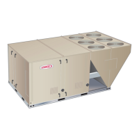
LGM SERIES
13 to 25 ton
45.7 to 88 kW
100024
Revised 08/2021
LGM156U through 300U
Question and Answer IconNeed help?

Do you have a question about the Lennox LGM180 and is the answer not in the manual?

Lennox LGM180 Specifications

General IconGeneral
BrandLennox
ModelLGM180
CategoryFurnace
LanguageEnglish

Summary

Specifications - Cooling Performance

Cooling Performance Specifications

Performance data for cooling operation.

Refrigerant Charge Specifications

Refrigerant charge details for various conditions.

Indoor Blower and Drive Specifications

Specifications for the indoor blower and drive.

Specifications - Gas Heat

Two-Stage Gas Heat Performance

Performance data for two-stage heating.

Four-Stage Gas Heat Performance

Performance data for four-stage heating.

Blower Data

Electrical Data - 13 Ton

Electrical Data - 17.5 Ton & 20 Ton

Electrical Data - 25 Ton

Unit Components

Burner Controls A3 & A12

Description of burner control modules.

Variable Frequency Drive A96

Details on the optional VFD.

Unit Controller A55

Overview of the main unit controller.

Compressor 3 & 4 Controllers

Description of compressor controllers.

Blower Motor Overload Relay S42

Description of the blower motor overload relay.

Telemecanique Overload Relay

Details on the Telemecanique overload relay.

Siemens Overload Relay

Details on the Siemens overload relay.

Cooling Components

Compressors

Description of compressors used in the units.

High Pressure Switches

Description of high pressure switches.

Low Pressure Switches

Description of low pressure switches.

Indoor Blower Motor B3

Description of the indoor blower motor.

Operation and Adjustment

Blower Access

Procedure for accessing the blower assembly.

Determining Unit CFM

Procedure for setting and verifying unit CFM.

Blower Belt Adjustment

Instructions for adjusting blower belt tension and alignment.

Blower Assembly (No Tensioner)

Details on blowers without a belt tensioner.

Pulley Alignment (No Tensioner)

Visual guide for pulley alignment without a tensioner.

Pulley Alignment (With Tensioner)

Visual guide for pulley alignment with a tensioner.

Pulley Alignment with Tensioner

Detailed steps for pulley alignment with a tensioner.

Blowers With Belt Tensioner

Instructions for blowers equipped with a tensioner.

Check Belt Tension

Procedure for checking and measuring belt tension.

Measure Belt Tension

Guide on measuring belt tension force.

Gas Heat Components

Burner Ignition Controls

Description of burner ignition controls.

Normal Ignition Sequence Timings

Nominal timings for the normal ignition sequence.

Ignition Attempt Sequence Timings

Nominal timings for ignition attempts with retrials.

Placement and Installation

Refrigerant Charging

Procedures for checking refrigerant charge.

Approach Method Verification

Verification using approach method.

Startup and Operation

Preliminary and Seasonal Checks

Pre-operation checks and maintenance.

Cooling Startup Procedure

Steps to start the unit in cooling mode.

Heating Startup Procedure

Steps to start the unit in heating mode.

Furnace Operation

Procedures for operating the furnace.

Safety Shutdown

Emergency shutdown procedures.

System Service Checks

Heating System Service Checks

Procedures for checking the heating system.

Cooling System Service Checks

Procedures for checking the cooling system.

Maintenance

Control Systems

A55 Unit Controller

Description of the A55 Unit Controller.

Factory-Installed Hot Gas Re-Heat

Reheat Setpoint Adjustment

How to adjust the reheat setpoint.

Hot Gas Re-Heat Check-Out

Procedure for testing hot gas reheat operation.

Reheat Operation Modes

Different modes of reheat operation.

Multi-Staged Blower Operation

Setting Maximum CFM

Procedure for setting maximum CFM.

Setting Blower Speeds

Procedure for setting blower speeds.

Setting Damper Minimum Position

Procedure for setting damper minimum positions.

Inverter Bypass Option

Instructions for bypassing the inverter.

VAV System Operation

VAV System Startup

Startup procedures for the VAV system.

VAV System Unit Operation

Operating the VAV system.

Manual VFD Bypass

Procedure for manual VFD bypass.

Wiring Diagrams and Sequence of Operation

Gas Heat Diagram

Wiring diagram for gas heat operation.

Gas Heat Sequence of Operation (156/300)

Step-by-step operation for gas heat.

Thermostat Wiring Diagram

Wiring diagram for thermostat connections.

Economizer Wiring Diagram

Wiring diagram for the economizer system.

Operation Sequence (LGM/LCM156/180)

Sequence of operation for LGM/LCM156/180 units.

Wiring Diagram (210-300V No Bypass)

Wiring diagram for specific models and configuration.

Wiring Diagram (210-300 G No Bypass)

Wiring diagram for specific models and configuration.

Wiring Diagram (210-300 Y With Bypass)

Wiring diagram for specific models and configuration.

Wiring Diagram (210-300 G With Bypass)

Wiring diagram for specific models and configuration.

Operation Sequence (LGM/LCM210-300)

Sequence of operation for LGM/LCM210/240/300 units.

Economizer Operation

Sequence of economizer operation.

First Stage Cooling Operation

Sequence for first stage cooling.

Second Stage Cooling Operation

Sequence for second stage cooling.

Blower Operation With Bypass

Blower operation with bypass.

Blower Operation No Bypass

Blower operation without bypass.

Related product manuals