Page 51
B-Unit Operation
Use the mobile app to check unit mechanical operation.
See the Service - Test section of the Unit Controller man-
ual.
C-Manual Supply Air VFD Bypass
IMPORTANT - All dampers must be open to prevent
damage to duct work and dampers.
Note - This section does not apply to units equipped with
optional automatic VFD bypass. That option will automat-
ically change from multi-stage air volume to constant air
volume operation in the event of VFD failure.
Manually change blower operation to constant air volume
as follows:
1 - Disconnect all power to unit and WAIT AT LEAST
10 MINUTES before opening the VFD cover.
WARNING
ELECTRICAL SHOCK HAZARD.
STOP! Before you continue, make sure
at least 10 minutes. The capacitor in
the VFD holds high voltage power for
up to 10 minutes after power has been
disconnected.
2 -
3 -
4 -
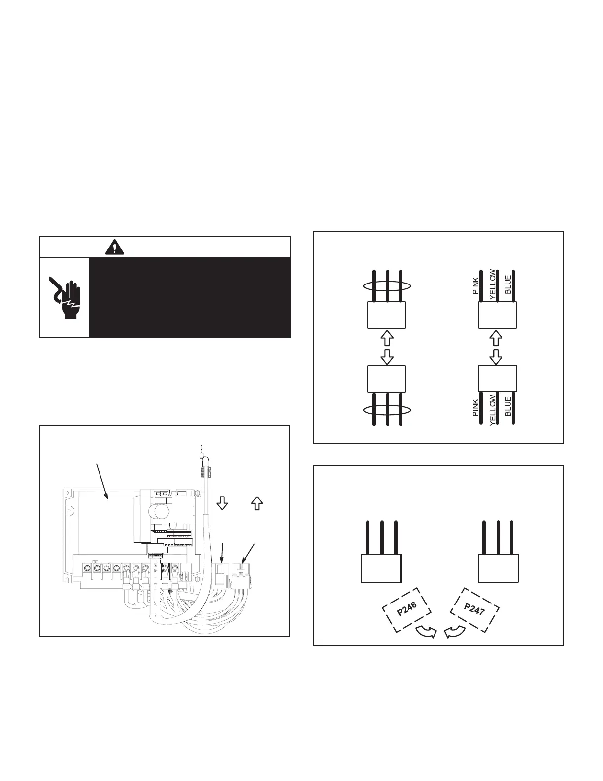
A96
SUPPLY AIR VFD
P247P246
POWER
IN, TO
VFD
POWER
OUT, TO
BLOWER
FIGURE 38
5 - Restore power to unit. Blower will operate in
constant air volume (CAV) mode.
Note - The indoor blower motor will start as soon as
the main unit power is restored. In manual bypass,
the blower will run regardless of thermostat signals
until main unit power is turned o. Manual bypass is
meant for emergency operation only and not long-
term usage.
Check the indoor blower motor nameplate for full
load amperage (FLA) value. Measure the amp
readings from the indoor blower motor operating
in bypass mode. If measured amps are higher
than nameplate FLA value, decrease the CFM
by opening (turning counterclockwise) the motor
maximum number of pulley turns as shown in table
5.
P247
DISCONNECT VFD BYPASS CONNECTORS
P246
P246
P247
POWER IN TO VFD
POWER IN TO VFD
POWER OUT, TO BLOWER
POWER OUT, TO BLOWER
PINK
WIRES
PINK
WIRES
FIGURE 39
CONNECT POWER DIRECTLY TO BLOWER
(BYPASS VFD)
P246
P247
POWER IN TO VFD POWER OUT, TO BLOWER
FIGURE 40
 Loading...

