15-Second-Stage Power Exhaust Relay K231
(Staged-Blower units equipped with power exhaust)
of full speed (adjustable ECTO). This prevents a nega-
tive building pressure when the blower is operating in low
speed. Refer to the Unit Controller manual and ECTO la-
bels on the unit.
15-Fuse F61 (Higher SCCR units only)
provides overcurrent protection to compressor and other
sheet metal enclosure in the unit left front corner mullion.
16-Blower Motor Overload Relay S42
The relay (S42) is connected in line with the blower motor
contacts open to de-energize pin #1 in plug P299 of the
A55 Unit Controller. A55 de-energizes all outputs. Units
will be equipped with a relay manufactured by Teleme-
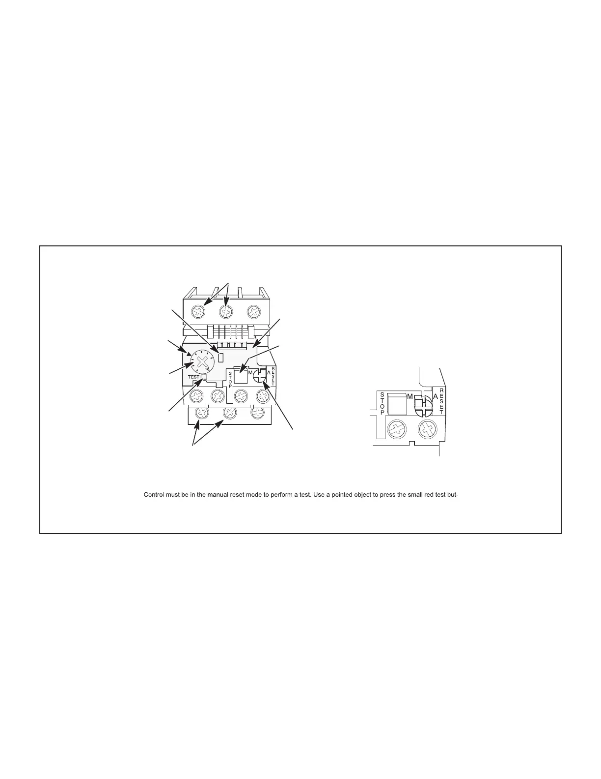
CLEAR
COVER
(SHOWN
CLOSED)
STOP
BUTTON
(RED)
RED TEST
BUTTON
(Push To Test)
AMP SETTING
CONTROL
(BLUE DIAL)
TRIP
INDICATION
WINDOW
LINE VOLTAGE IN
AMP SETTING
POINTER
BLUE RESET SCREW
(Shown in AUTO position as
shipped from the factory)
LOAD VOLTAGE
OUT
DETAIL SHOWING RESET BUTTON
ADJUSTED TO MANUAL POSITION
Lift clear cover and turn adjustment screw
counterclockwise. Reset screw will pop out
when pointer is in M (manual position). Close
cover to lock reset screw into position.
TELEMECANIQUE OVERLOAD RELAY
Lift clear cover to adjust relay amp setting according to value given on the blower motor nameplate. Proper relay
amp setting equals motor nameplate FLA X service factor of 1.15 X .95.
Cover must also be lifted to adjust control mode from automatic reset to manual reset (see detail above) and to
test the control.
ton. A yellow marker should appear in the trip indication window to the right of the amp setting control. Press the
blue reset screw to reset the relay.
The red STOP button opens the normally closed contacts which power the blower motor. This button stops blower
motor operation as long as it is pressed in.
FIGURE 5
 Loading...


