Page 24
B-Blower Access
1 - Disconnect jack/plug connector to blower motor.
Also disconnect jack/plug connector heating limit
switches on gas units.
2 - Remove screws on either side of blower assembly
3 - Pull base toward outside of unit.
C-Determining Unit CFM
IMPORTANT - Multi-staged supply air units are factory-set
to run the blower at full speed when there is a blower (G)
demand without a heating or cooling demand. Refer to the
eld-provided, design specied CFM for all modes of op-
eration. Use the following procedure to adjust motor pulley
to deliver the highest CFM called for in the design spec.
See Inverter Start-Up section to set blower CFM for all
modes once the motor pulley is set.
1 - The following measurements must be made with
a dry indoor coil. Run blower (G demand) without
a cooling demand. Measure the indoor blower
measurements are taken.
2 -
Blower performance data is based on static pressure
Note - Static pressure readings can vary if not taken
where shown.
3 - See table of contents for Blower Data and or
Optional Accessories. Use static pressure and RPM
readings to determine unit CFM.
4 - The blower RPM can be adjusted at the motor pulley.
Loosen Allen screw and turn adjustable pulley
clockwise to increase CFM. Turn counterclockwise
shown in table 4.
TABLE 4
Belt Min Turns Open
A Section No Minimum 5
B Section 1*
*No minimum number of turns open when B belt is used
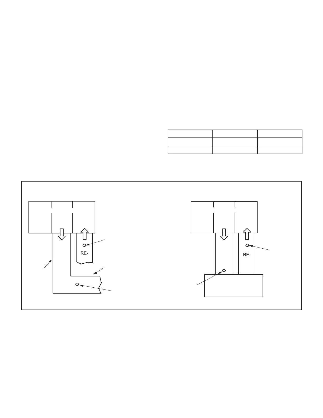
LOCATION OF STATIC PRESSURE READINGS
SUPPLY AIR
READING
LOCATION
SUPPLY
TURN
INSTALLATIONS WITH DUCTWORK
SUPPLY
TURN
INSTALLATIONS WITH CEILING DIFFUSERS
MAIN
DUCT RUN
FIRST BRANCH
OFF OF MAIN RUN
DIFFUSER
ROOFTOP UNIT
ROOFTOP UNIT
SUPPLY AIR
READING
LOCATION
RETURN AIR
READING LOCATION
RETURN AIR
READING
LOCATION
FIGURE 11
 Loading...


