Page 13
3- Connect thermostat wiring to Unit Controller on the
lower side of the controls hat section.
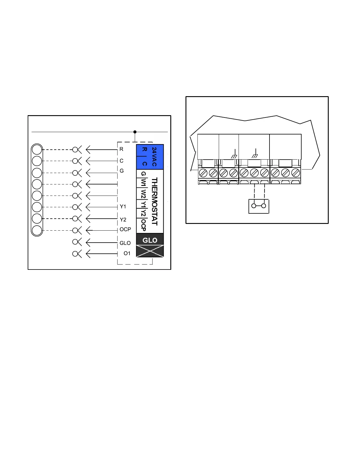
4- Wire as shown in figure 15 for electro-mechanical
and electronic thermostats. If using other
temperature control devices or energy management
systems see instructions and wiring diagram
provided by manufacturer.
IMPORTANT-Terminal connections at the Unit Controller
must be made securely. Loose control wire connections
may allow unit to operate but not with proper response to
room demand.
D
FIGURE 15
24 VOLT FIELD WIRING IN THERMOSTAT MODE
J262C
10
11
12
P297
J297A
1
2
B
3
4
5
6
7
8
C
9
10
24 V POWER
W1
W2
P262
A55
R
OCP
C
G
W1
W2
Y1
Y2
Zone Sensor Mode
The Unit Controller will operate heating and cooling
based on the Unit Controller internal setpoints and the
temperature from the A2 room sensor. An optional
Network Control Panel (NCP) can also be used to provide
setpoints. A thermostat or return air sensor can be used
as a back-up mode. Make room sensor wiring
connections as shown in figure 16.
FIGURE 16
FIELD WIRING IN ZONE SENSOR MODE
(Zone Sensor Mode)
A2 SENSOR
INPUTS
SENSOR
SENSOR
24VAC
RC
IAQ
HUM
AI1
AI2
TMP
R
UNIT CONTROLLER
J298
C
 Loading...