Page 30
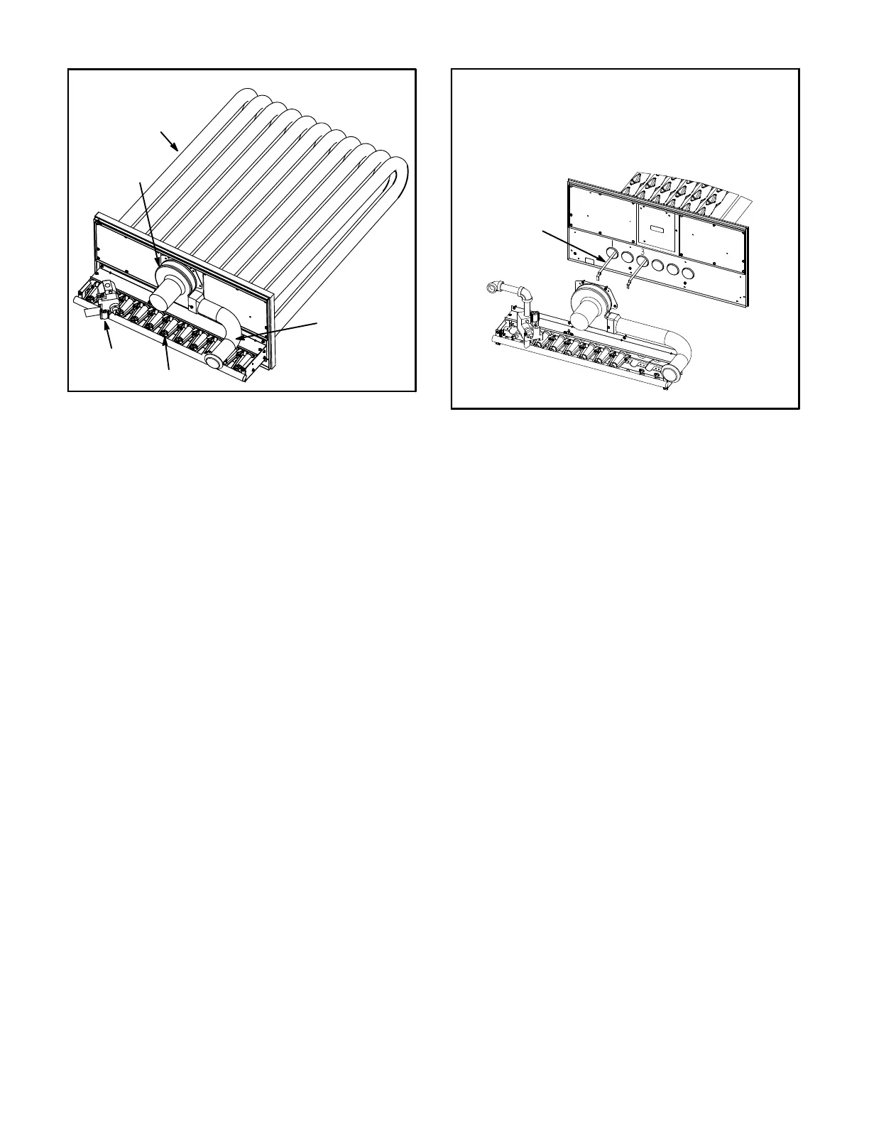
HEAT EXCHANGER ASSEMBLY
FIGURE 29
BURNER
COMBUSTION
AIR INDUCER
VENT
CONNECTOR
GAS VALVE
HEAT
EXCHANGER
TUBE
E-Flue Passageway and Flue Box (Gas Units)
1- Remove combustion air inducer assembly as
described in section D.
2- Remove flue box cover. Clean with a wire brush as
required.
3- Remove inserts if installed. See figure 30.
4- Clean tubes with a wire brush.
5- Reassemble the unit. The flue box cover gasket and
combustion air inducer gasket should also be
replaced during reassembly.
F-Gas Heat Exchanger Inserts
Inserts are installed on standard (130,000Btuh) and high
(240,000Btuh) heat exchangers. Medium heat
exchangers do not require inserts. See figure 30.
STANDARD HEAT (130,000BTUH)
FIGURE 30
INSERTS (2)
Note - No inserts on
medium and high heat.
INSERT LOCATION
G-Indoor Coil
Inspect and clean coil at beginning of each cooling season.
Clean using mild detergent or commercial coil cleaner.
Flush coil and condensate drain with water taking care not
to get insulation, filters and return air ducts wet.
H-Supply Air Blower Wheel
Annually inspect supply air blower wheel for accumulated
dirt or dust. Turn off power before attempting to remove
access panel or to clean blower wheel.
J-Outdoor Coil
Clean outdoor coil annually with detergent or commercial
coil cleaner and inspect monthly during the cooling
season. Access panels are provided on front and back of
outdoor section.
K-Needlepoint Bipolar Ionizer
The ionizer was designed for low maintenance. The
device should be checked semi-annually to confirm the
brushes are clean for maximum output. The ionizer is
located on the blower deck. See figure 31.
 Loading...