Page 32
L-UVC Light
When field-installed, use only UVC Light Kit assembly
106882-01 (21A93) with this appliance.
Factory-Installed UVC Light
When the UVC light is factory installed, the lamp is
shipped in a foam sleeve. The lamp is attached to the
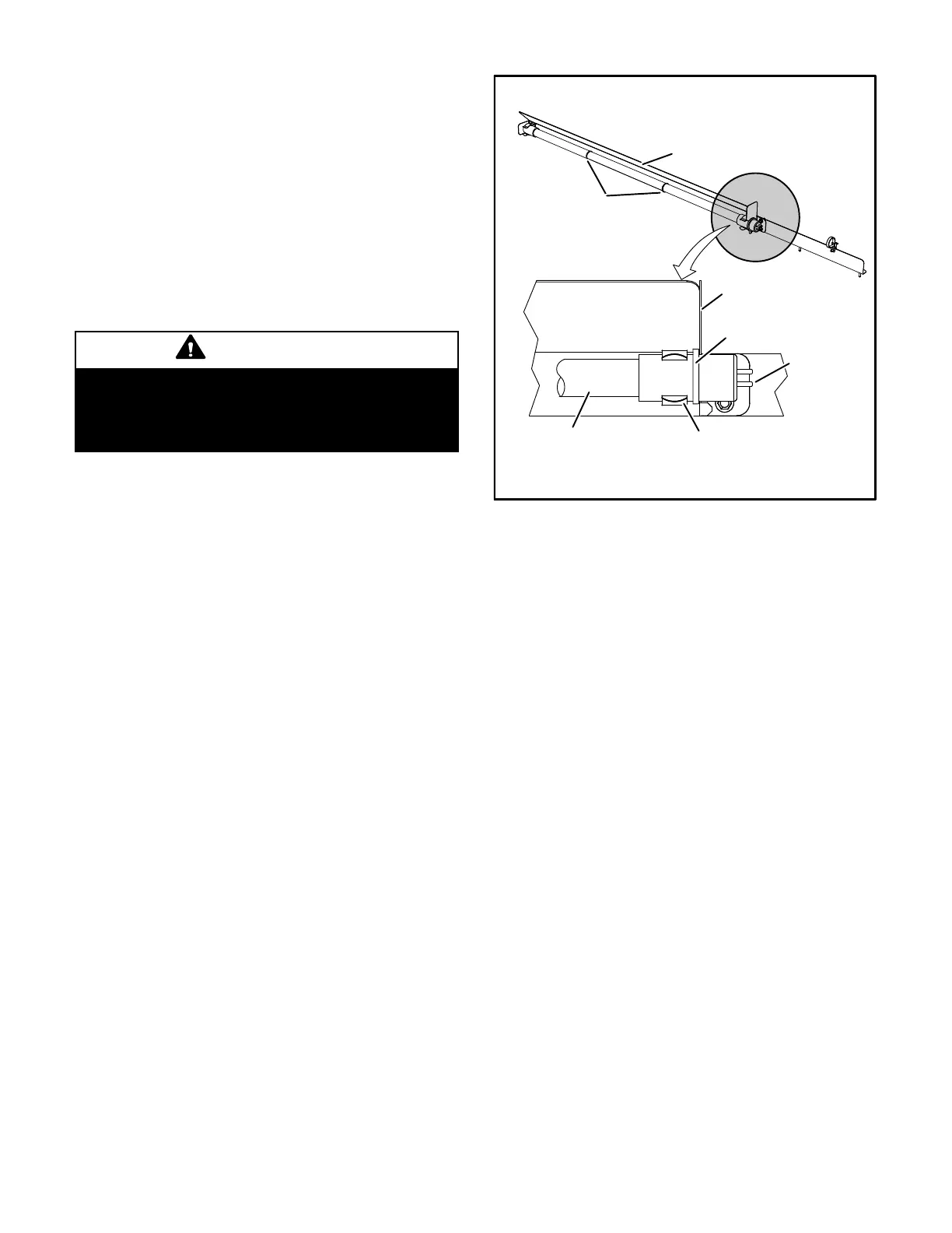
UVC light assembly on the blower deck. See figure 32.
Remove the lamp and install into the UVC light assembly
as shown in steps 2 through 11.
Annual Lamp Replacement
WARNING
Personal Burn Hazard.
Personal injury may result from hot lamps. During
replacement, allow lamp to cool for 10 minutes be
fore removing lamp from fixture.
The lamp should be replaced every 12 months, as UVC
energy production diminishes over time.
1- Obtain replacement lamp 101087-01 for your
germicidal light model.
2- Disconnect power to the rooftop unit before servicing
the UVC kit.
3- Open the blower access door.
4- Remove the screw in wire tie from the UVC assembly
and disconnect the 4-pin connector from the lamp end.
5- Remove and retain the (3) screws securing the UVC
assembly. Carefully slide the complete UVC
assembly out through the blower access door. See
figure 32.
6- Allow 10 minutes before touching the lamps. Then,
carefully remove the old lamp from the lamp holder
clips.
7- Wear cotton gloves or use a cotton cloth when
handling the new lamp. Place the new lamp in the
holder clips of the UVC assembly. Verify that the lamp
flange at the connector end is sandwiched between
the lamp holder clip and the sheet-metal end stop
(see figure 33).
8- Carefully place the UVC assembly on the blower
deck. Line up the mounting holes on the UVC
assembly with the mounting holes on the blower deck
See figure 32. Use the retained screws provided to
attach the UVC assembly in place.
9- Close the blower access door.
10- Reconnect power to the rooftop unit.
11- Open the filter access door and look through the view
port in the triangular sheet-metal panel to verify that
the UVC light is on.
FIGURE 33
LAMP
FLANGE
4-PIN
CONNECTOR
HOLDER
CLIPS (2)
SHEET METAL
END STOP
DETAIL A
BANDS (see
Note below)
UVC
Sub-Assembly
LAMP
NOTE - The bands around the lamp should be evenly spaced
as shown in the diagram.
INSTALL LAMP IN HOLDER CLIPS
If UVC lamp does not come on:
1- Check Power Wiring: Disconnect 1/4” QC (quick
connects) of the UVC cable near the UVC assembly.
With Power ON, use multimeter to test 110-230V at
the 1/4”QC quick connects from the control panel.
2- Check Lamp: Carefully remove the UVC assembly
out of the rooftop unit. Use multimeter to test for
continuity across each pair of pins at each end of the
lamp.
3- Check Lamp Installation: Make sure that lamp's pins
snap properly into the lamp holder.
LED(s) not illuminated
Power status LED not lit—Check that the lamp unit is
connected to the proper power source and is wired
correctly.
Lamp status LED(s) not lit—
1- Check that lamp 4-pin connectors are properly
engaged.
2- Ohm-check across the lamp pins to check for
continuity of lamp filaments (see figure 35).
Troubleshooting charts are provided to aid in determining the
cause of any problems encountered (figures 34 and 35).
Lamp Disposal
Hg-LAMP Contains Mercury.—Manage in accordance
with local, state and federal disposal laws. Refer to
www.lamprecycle.org or call 800-953-6669.
 Loading...