Page 17
Condenser coil may need to be cleaned at startup in
case oil from the manufacturing process is found on the
condenser coil.
Burners
To clean the burners, rst remove them from the furnace
as explained in the Burner and Burner Orice Instructions
section. Vacuum and/or brush as required.
Vent Outlet
Visually inspect vent outlet periodically to make sure that
there is no buildup of soot or dirt. If necessary, clean to
maintain adequate opening to discharge ue products.
Heat Exchanger
With proper combustion adjustment, the heat exchanger
of a gas-red furnace will seldom need cleaning. Sooting
of a gas appliance is highly irregular and once cleaned,
the cause of the sooting must be determined. If the heat
exchanger should become sooted, it can be cleaned as
follows:
1. Remove the burner assembly as outlined in the Burner
and Burner Orice Instructions section.
2. Remove the combustion blower.
3. At the bottom of the heating section, remove the screws
holding the ue collector box. Carefully remove the ue
collector box without ripping the adjacent insulation.
4. Using a wire brush on a exible wand, brush out the
inside of each heat exchanger from the burner inlet
and ue outlet ends.
5. Brush out the inside of the ue collector box.
6. Run the wire brush down the heat exchanger tubes
from the ue collector end.
7. If soot buildup is excessive, remove the vent motor and
clean the wheel and housing. Run the wire brush down
the ue extension at the outlet of the vent housing.
8. After brushing is complete, blow all brushed areas with
air. Vacuum as needed.
9. Replace parts in the reverse order they were removed
in Steps 1 through 3.
10. When replacing the ue collector box, be careful so as
not to tear the adjoining insulation.
11. Assure that all joints on the vent side of the combustion
system are air tight. Apply a high temperature (+500°F)
sealing compound where needed.
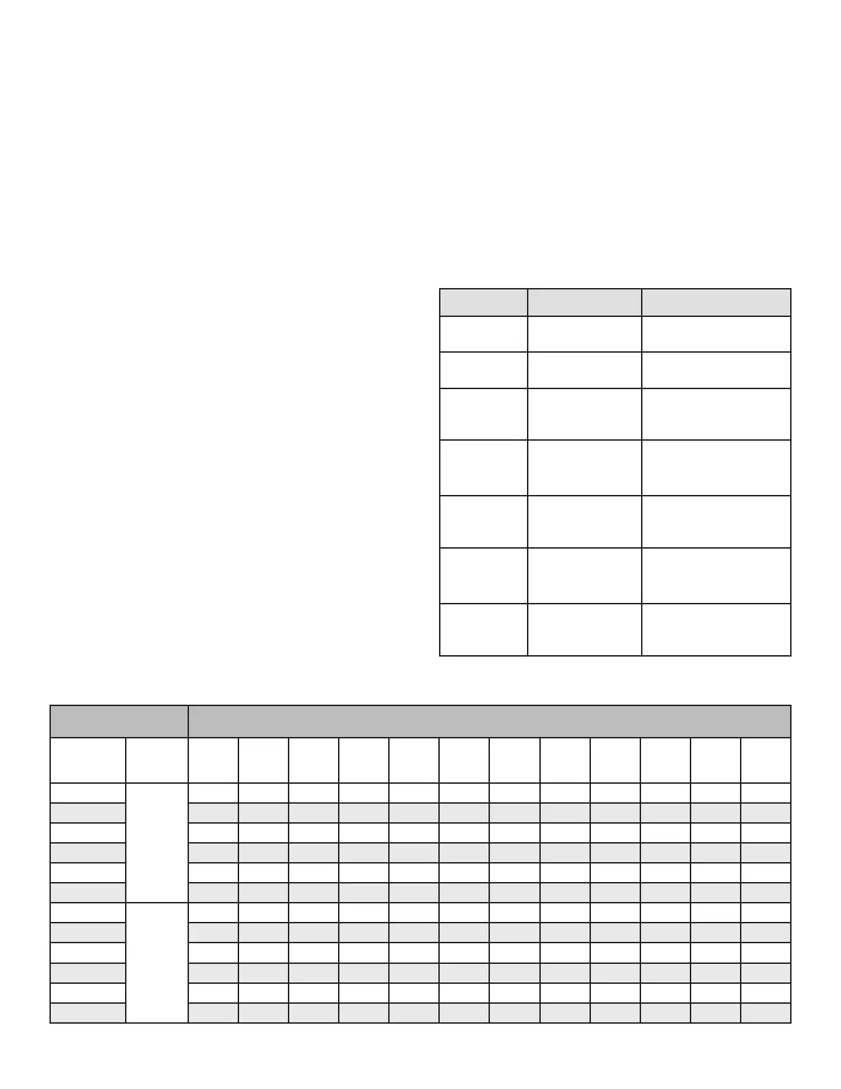
Control System Diagnostics
Table 4. Fault Codes
LED Status Flashing Rate Fault Description
Slow Flash
One ash per
second
Normal operation:
No call for heat
Fast Flash
Two ashes per
second
Normal operation:
Call for heat
2 Flash
Two ashes in
second with
1-second pause
System lockout:
Failed to detect or
sustain ame
3 Flash
Three ashes in
1.5 seconds with
1-second pause
Pressure switch senses
incorrect pressure or gas
valve coil is open.
4 Flash
Four ashes in
2 seconds with
1-second pause
High limit or rollout
switch open
5 Flash
Five ashes in
2.5 seconds with
1-second pause
Flame sensed and gas
valve not energized
Steady --
Internal failure:
Micro-controller failure;
self-check
Table 5. Cooling Performance - Gas/Electric Models
80 DB / 67 WB Deg.
Return Air
Air Temperature Entering Evaporator Coil, Degree F
Cooling
Input
(1000 BTU)
Pressure 65° 70° 75° 80° 82° 85° 90° 95° 100° 105° 110° 115°
24
Suction
135 136 137 139 139 141 143 146 148 150 152 154
30 135 137 140 142 143 145 147 150 152 154 155 157
36 135 137 140 142 143 144 147 149 151 152 154 155
42 129 132 135 139 140 141 143 145 146 147 148 149
48 132 136 139 143 144 145 146 147 149 151 152 154
60 130 131 133 134 135 136 139 141 144 146 149 152
24
Liquid
250 266 282 298 304 318 340 363 388 413 438 463
30 247 269 292 314 323 336 358 380 406 432 457 483
36 250 275 301 326 336 351 375 399 423 446 470 493
42 248 271 293 316 325 339 362 385 411 436 462 487
48 265 286 308 329 338 352 376 400 427 455 482 509
60 256 276 296 316 324 340 365 386 415 438 473 503