Page 48
3 - Select indoor blower speed tap, which provides a
temperature rise within the range specied on the
rating plate.
4 - Verify manifold gas pressure
NOTE: For purpose of this measurement, the minimum
permissible gas supply pressure is 5” w.c. for natural gas.
a. Slide the gas valve switch to the “OFF” position (see
Figure 24).
b. Remove plug on valve marked “OUTLET PRESSURE.”
c. Install a water manometer.
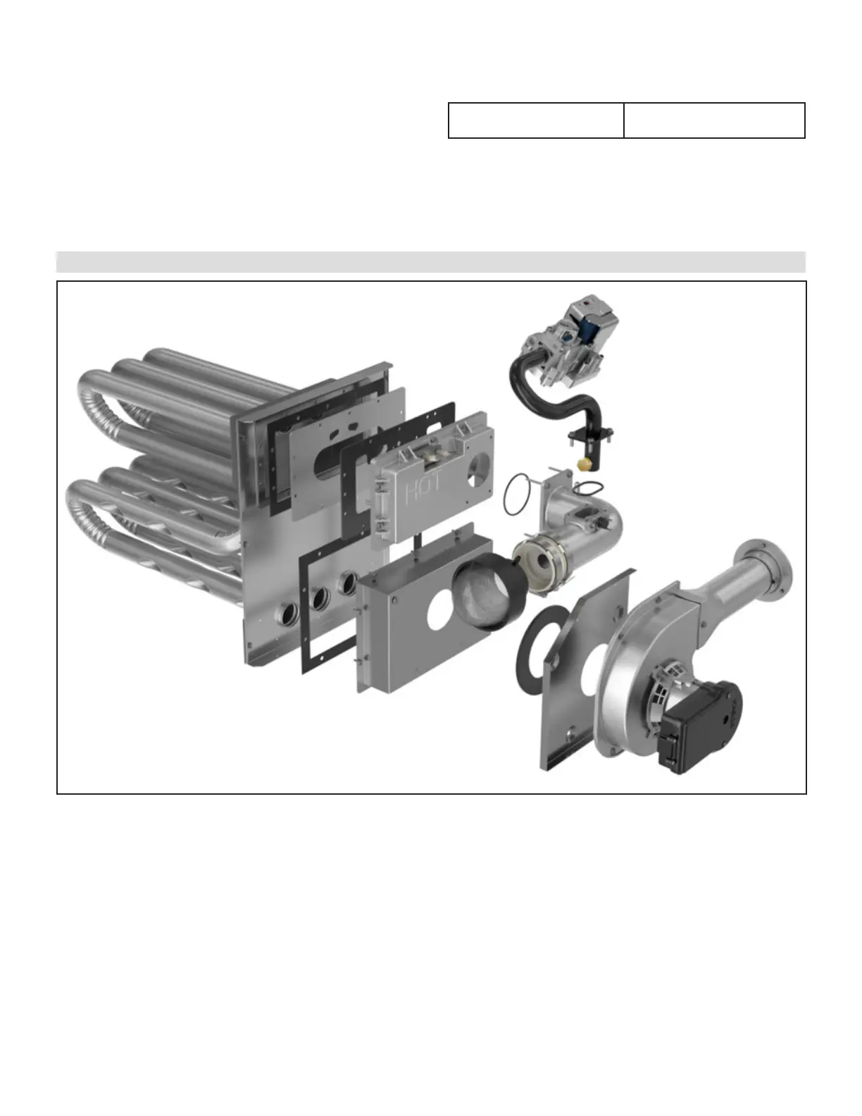
Heat Exchanger
d. Slide the gas valve switch to the “ON” position and initi-
ate a call for heat. During steady state operation, mani-
fold pressure should be:
Manifold Pressure
(non-adjustable)
2.7 - 3.1" w.c.
e. After verifying pressure, turn gas o, remove manome-
ter tting, and replace pipe plug and regulator cap.
f. Put unit in operation and check plug for leaks using
soapy solution.
FIGURE 28. Gas Valve, Manifold and Heat Exchanger Assembly