Installation - Operation - Maintenance manual • CHILLERS • ANNEXES - 0105-E • 53 •
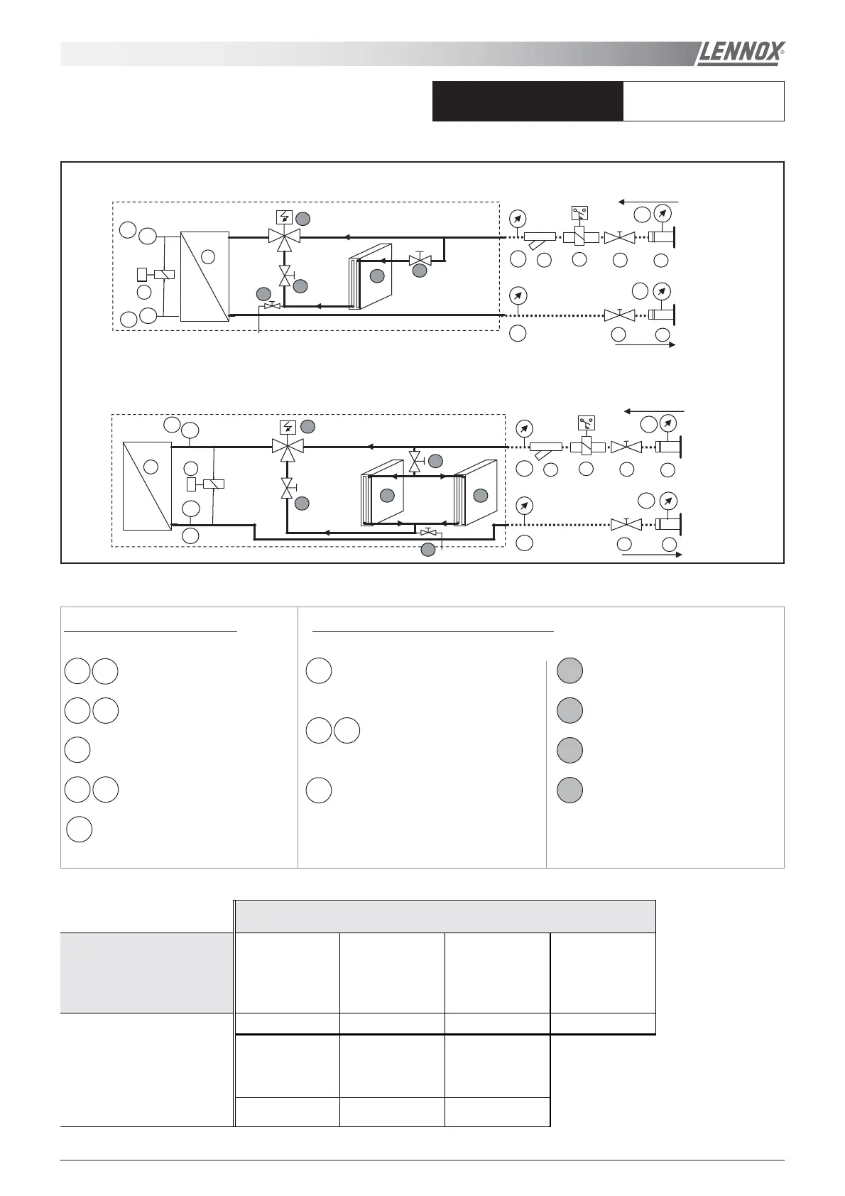
ECOLOGIC - HYDRAULIC DRAWING
UNIT WITH FREE COOLING OPTION
01
0203
19
18
22
16
04a
04b
17a
17b
01
02
03
19
18
22
16
04a
04b
17a
17b
°C
°C
15b
15a
°C
15a
°C
15b
05
05
B
C
D
B
A A
D
C
B
B
A
ITEMS SUPPLIED LOOSE
std/ln/he/sln
wa - ek - dk
ITEMS MOUNTED INSIDE THE UNIT
OPTIONS
BASIC UNIT Water inlet filter
Paddle flow switch
Supplied loose
Differential flow
switch
Supplied mounted
Unit isolation valve
Add 03 Add 05 Add 22 Add 02/18
Kit for groove lock
coupling
Inlet/Outlet
manometer
Inlet/outlet
manometer + kit
for groove lock
coupling
16
15a/15b
Add 01/19 Add 04a/17a
Add 04b/17b and
01/19
WA 150 STD/LN
WA 150 HE/SLN and 200/230/270/300/370 STD/LN/HE/SLN
Groove lock coupling
01
19
Unit isolation valve
02 18
Water inlet filter
03
In/Out manometers without
groove lock coupling option
04a 17a
Paddle flow switch mounted on
tube
05
Flow switch/differential
22
Temperature sensors15a 15b
Plate heat exchanger
16
Drain
D
Three way valve
C
Isolating valves
B
Free cooling coil
A
 Loading...