TWOPIECE (UncasedCoilShown)
PATCH PLATE
tNCASED COIL
ONLY) LIQUID LINE
..._ORIFICE STUB END
HOUSING
DISTRIBUTOR TXV
TUBES. -
RING
MALE EQUALIZER LINE
FITTING (SEE SUCTION
FIGURE 22 FOR LINE
FURTHER DETAILS)
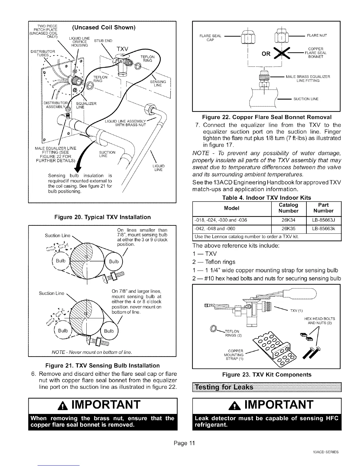
Sensing bulb insulation is
required if mounted external to
the coil casing. See figure 21 for
bulb positioning,
LIQUID
LINE
Figure 20. Typical TXV Installation
On lines smaller than
Suction Line, 718", mount sensing bulb
at either the 3 or 9 o'clock
position,
/
Bulb
\
Suction Line
_2_"Y A,.\\",_ t
(Bulb .
On 7/8" and larger lines,
mount sensing bulb at
either the 4 or 8 o'clock
position, never mount on
mof line.
NO TE - Never mount on bottom of line.
Figure 21. TXV Sensing Bulb Installation
6, Remove and discard either the flare seal cap or flare
nut with copper flare seal bonnet from the equalizer
line port on the suction line as illustrated in figure 22.
IMPORTANT
FLARE SEAL
CAP
,_ [__FLARE NUT
I X COPPERE OR --FLARE SEAL
BONNET
I
-- MALE BRASS EQUALIZER
_ LINE FITTING
SUCTION LINE
Figure 22. Copper Flare Seal Bonnet Removal
7, Connect the equalizer line from the TXV to the
equalizer suction port on the suction line. Finger
tighten the flare nut plus 1/8 turn (7 ft-lbs) as illustrated
in figure 17,
NOTE - To prevent any possibility of water damage,
properly insulate all parts of the TXV assembly that may
sweat due to temperature differences between the valve
and its surrounding ambient temperatures,
See the 13ACD Engineering Handbook for approved TXV
match-ups and application information.
Table 4. Indoor TXV Indoor Kits
Model Catalog Part
Number Number
-018, -024, -030 and -036 26K34 LB-85663J
-042, -048 and -060 26K35 LB-85663k
Use the Lennox catalog number to order a TXV kit.
The above reference kits include:
1 -- TXV
2 -- Teflon rings
1 -- 1 1/4" wide copper mounting strap for sensing bulb
2 --#10 hex head bolts and nuts for securing sensing bulb
AND NUTS (2)
O_TEFLON
RINGS (2) _ _//7
J
STRAP (1) _
Figure 23. TXV Kit Components
Xk IMPORTANT
Page 11
13ACD SERIES
 Loading...