DESCRIPTION
MP N NT
A4 i]ONTROL-TIMED OFF
_I i]OMPRESSOR
54 i_OTOR-OUTDOOR FAN
_12 i]APACITOR-DUAL
HRI i4EATER-COMPRESSOR
KI.-liCONTACTOR-COMPRESSOR
$4 iSWlTCH-HIGH PRESSURE
587 i_WITCH-LOW PRESS.COMP I
INDICATES OPTIONAL
COMPONENTS
./_ FOR USE WITH COPPER
CONDUCTORS ONLY. REFER
TO UNIT RATING PLATE
FOR MINIMUM CIRCUIT
AMPACITY AND MAXIMUM
OVERCURRENT PROTECTION
SIZE,
Z_ JUMPER IS USED WHEN TOC IS NOT USED
WARNING-
ELECTRIC SHOCK HAZARD, CAN CAUSE
INJURY OR DEATH, UNIT MUST BE
GROUNDED IN ACCORDANCE WITH
NATIONAL AND LOCAL CODES.
_LINE VOLTAGE FIELD INSTALLED
I III CLASS II VOLTAGE FIELD INSTALLED
OUTDOOR
PURPLE
CLACK
ORANGE
RED
COMPRESSOR
CRANKCASE HEATER
DUAL
CAPACITOR
CONTACTOR
OROUND
LUG
208-23016011
L2.,_
_-_EOUIPMENT
= GROUND
A4
TIMED OFF
CONTROL
I I I
-L4_
I I
TO 24 VAC POWER
SOURCE
20 VA MINIMUN
NEC CLASS 2
HRI
r_
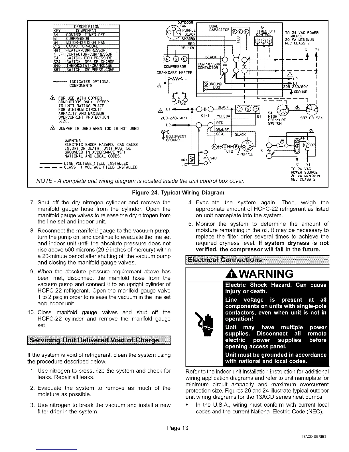
NOTE - A complete unit wiring diagram is located inside the unit control box cover.
KI-I YELLOWl I IBt HIBF 587 OR SZ4
o-oiRE°I i SW,TcHPRESSORE
$ (I ]ORANGEI .
C YI
TO 24 VAC
P_ER SOURCE
20 VA MINIMUN
NEC CLASS 2
Figure 24. Typical Wiring Diagram
7. Shut off the dry nitrogen cylinder and remove the
manifold gauge hose from the cylinder. Open the
manifold gauge valves to release the dry nitrogen from
the line set and indoor unit,
8. Reconnect the manifold gauge to the vacuum pump,
turn the pump on, and continue to evacuate the line set
and indoor unit until the absolute pressure does not
rise above 500 microns (29.9 inches of mercury) within
a 20-minute period after shutting off the vacuum pump
and closing the manifold gauge valves.
9. When the absolute pressure requirement above has
been met, disconnect the manifold hose from the
vacuum pump and connect it to an upright cylinder of
HCFC-22 refrigerant. Open the manifold gauge valve
1 to 2 psig in order to release the vacuum in the line set
and indoor unit,
10. Close manifold gauge valves and shut off the
HCFC-22 cylinder and remove the manifold gauge
set,
If the system is void of refrigerant, clean the system using
the procedure described below.
1. Use nitrogen to pressurize the system and check for
leaks, Repair all leaks,
2. Evacuate the system to remove as much of the
moisture as possible,
3. Use nitrogen to break the vacuum and install a new
filter drier in the system.
4. Evacuate the system again. Then, weigh the
appropriate amount of HCFC-22 refrigerant as listed
on unit nameplate into the system,
5. Monitor the system to determine the amount of
moisture remaining in the oil. It may be necessary to
replace the filter drier several times to achieve the
required dryness level. If system dryness is not
verified, the compressor will fail in the future.
I WARNING
Refer to the indoor unit installation instruction for additional
wiring application diagrams and refer to unit nameplate for
minimum circuit ampacity and maximum overcurrent
protection size. Figures 26 and 24 illustrate typical outdoor
unit wiring diagrams for the 13ACD series heat pumps.
• In the U.S,A., wiring must conform with current local
codes and the current National Electric Code (NEC),
Page 13
13ACD SERIES
 Loading...