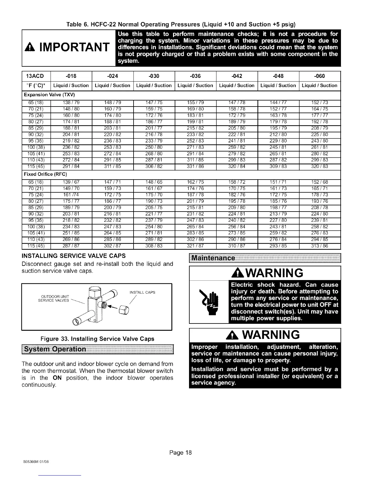
Table 6. HCFC-22 Normal Operating Pressures (Liquid +10 and Suction +5 psig)
A IMPORTANT
13ACD -018 -024 -030 -036 -042 -048 -060
°F (°C)* Liquid/Suction Liquid/Suction Liquid/Suction Liquid / Suction Liquid/Suction Liquid/Suction Liquid / Suction
Expansion Valve (TXV)
65 (18) 138 / 79 148 / 79 147 / 75 155 / 79 147 / 78 144 / 77 152 / 73
70 (21) 148 / 80 160 / 79 159 / 75 169 / 80 158 / 78 152 / 77 164 / 75
75 (24) 160 / 80 174 / 80 172 / 76 183 / 81 172 / 79 163 / 78 177 / 77
80 (27) 174 / 81 188 / 81 186 / 77 199 / 81 189 / 79 179 / 78 192 / 78
85 (29) 188 / 81 203 / 81 201 / 77 215 / 82 205 / 80 195 / 79 208 / 79
90 (32) 204 / 81 220 / 82 216 / 78 233 / 82 222 / 81 212 / 80 225 / 80
95 (35) 219 / 82 236 / 83 233 / 79 252 / 83 241 / 81 229 / 80 243 / 80
100 (38) 236 / 82 253 / 83 250 / 80 271 / 83 259 / 82 245 / 81 261 / 81
105 (41) 253 / 83 272 / 84 268 / 80 291 / 84 279 / 82 265 / 81 280 / 82
110 (43) 272 / 84 291 / 85 287 / 81 311 / 85 299 / 83 287 / 82 299 / 83
115 (45) 291 / 84 311 / 85 306 / 82 331 / 86 320 / 84 309 / 83 320 / 83
Fixed Orifice (RFC)
65 (18) 139 / 67 147 / 71 148 / 65 162 / 75 158 / 72 151 / 71 152 / 68
70 (21) 149 / 70 159 / 73 161 / 67 174 / 76 170 / 75 161 / 73 165 / 71
75 (24) 161 /74 172 / 75 175 / 70 187 / 78 182 / 76 172 / 75 178 / 73
80 (27) 175 / 77 186 / 77 190 / 73 201 / 79 195 / 78 185 / 76 193 / 76
85 (29) 189 / 79 200 / 79 205 / 75 215 / 81 209 / 80 198 / 77 208 / 78
90 (32) 203 / 81 216 / 81 221 / 77 231 / 82 224 / 81 213 / 79 224 / 80
95 (35) 218 / 82 232 / 82 237 / 79 247 / 83 240 / 82 227 / 80 239 / 81
100 (38) 234 / 83 247 / 83 254 / 80 265 / 84 256 / 84 243 / 81 258 / 82
105 (41) 251 / 85 264 / 85 271 / 81 283 / 85 273 / 85 259 / 82 276 / 83
110 (43) 269 / 86 285 / 86 289 / 82 302 / 86 290 / 86 276 / 84 294 / 85
115 (45) 287 / 87 302 / 87 308 / 83 321 / 87 310 / 87 293 / 85 313 / 86
INSTALLING SERVICE VALVE CAPS
Disconnect gauge set and re-install both the liquid and
suction service valve caps.
INSTALL CAPS
OUTDOOR UNIT
SERVICE VALVES _ /
Figure 33. Installing Service Valve Caps
The outdoor unit and indoor blower cycle on demand from
the room thermostat. When the thermostat blower switch
is in the ON position, the indoor blower operates
continuously.
I WARNING
WARNING
505366M 01/08
Page 18
 Loading...