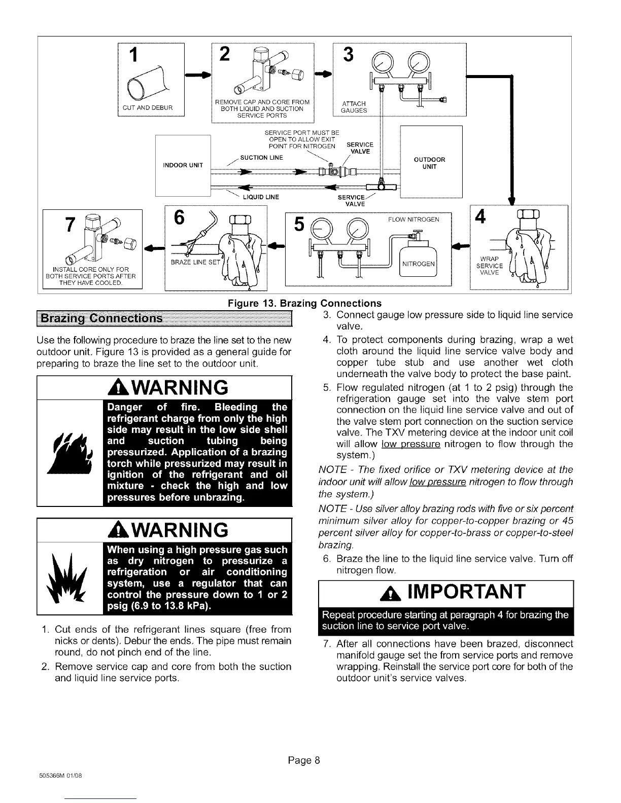
1
CUT AND DEBUR
INSTALL CORE ONLY FOR
BOTH SERVICE PORTS AFTER
THEY HAVE COOLED.
INDOOR UNIT
,4-,,
REMOVE CAP AND CORE FROM
BOTH LIQUID AND SUCTION
SERVICE PORTS
OUTDOOR
UNIT
SERVICE PORT MUST BE
OPEN TO ALLOW EXIT
POINT FOR NITROGEN SERVICE
/. SUCTION LINE _ /VALVE
LIQUtD LINE SERVICE/_
VALVE
RAP /_
SER
VALVE _
Use the following procedure to braze the line set to the new
outdoor unit, Figure 13 is provided as a general guide for
preparing to braze the line set to the outdoor unit,
A, WARNING I
WARNING
Figure 13. Brazing Connections
3. Connect gauge low pressure side to liquid line service
valve,
4, To protect components during brazing, wrap a wet
cloth around the liquid line service valve body and
copper tube stub and use another wet cloth
underneath the valve body to protect the base paint.
5, Flow regulated nitrogen (at 1 to 2 psig) through the
refrigeration gauge set into the valve stem port
connection on the liquid line service valve and out of
the valve stem port connection on the suction service
valve, The TXV metering device at the indoor unit coil
will allow low pressure nitrogen to flow through the
system,)
NOTE - The fixed orifice or TXV metering device at the
indoor unit will allow low pressure nitrogen to flow through
the system,)
NOTE - Use silver alloy brazing rods with five or six percent
i minimum silver alloy for copper-to-copper brazing or 45percent silver alloy for copper-to-brass or copper-to-steel
brazing.
6, Braze the line to the liquid line service valve, Turn off
nitrogen flow,
,A IMPORTANT
1. Cut ends of the refrigerant lines square (free from
nicks or dents). Debur the ends, The pipe must remain
round, do not pinch end of the line,
2. Remove service cap and core from both the suction
and liquid line service ports.
7. After all connections have been brazed, disconnect
manifold gauge set the from service ports and remove
wrapping. Reinstall the service port core for both of the
outdoor unit's service valves.
505366M 01/08
Page 8
 Loading...