Lennox Mini-Split Service Manual / Page 166
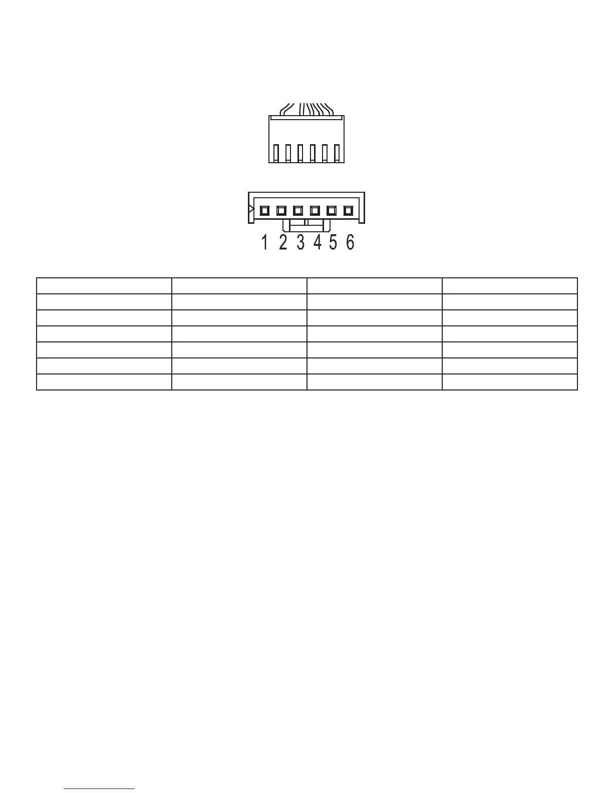
1. DC fan motor(control chip is inside fan motor)
Power on and while the unit is in standby, measure the voltage between pin1-pin3, pin4-pin3 at fan motor
connector.
If the value of the voltage is not in the range shown in below table, the PCB faulty and should be replaced.
DC motor voltage input and output
No. Color Signal Voltage
1 Red Vs/Vm 200~380V
2 --- --- ---
3 Black GND 0V
4 White Vcc 13.5~16.5V
5 Yellow Vsp 0~6.5V
6 Blue FG 13.5~16.5V
 Loading...