EasyManua.ls Logo

Lennox MWCA018S4-1P User Manual

Lennox MWCA018S4-1P
44 pages
To Next Page IconTo Next Page
Page #1 background imageLoading...
Page #1 background image
1
MINI-SPLIT SYSTEMS SERVICE MANUAL
MCA Series Unit Information
CORP1907-L5
11/2020
Supersedes 8/2019
Table of Contents
1. Indoor Units ................................................3
1.1. ModelNumberIdentication ................................... 3
1.2. IndoorUnitSpecications ....................................... 3
1.3. Indoor Unit Dimensions .......................................... 4
1.4. IndoorUnitClearances ........................................... 5
1.5. IndoorUnitWallMounts ......................................... 5
2. Indoor/Outdoor Matches ...........................6
3. Air Throw Data ...........................................6
4. Power and Communication Wiring for
Systems .....................................................7
4.1. Overview ................................................................. 7
4.2. WireGauge............................................................. 7
4.3. TerminalConnections ............................................. 8
5. Indoor Unit Diagrams ................................8
6. Wireless Remote ...................................... 10
6.1. Requirements ....................................................... 10
6.2. RemoteControlSpecications ............................. 10
6.3. FunctionButtons ................................................... 11
6.4. Display .................................................................. 12
6.5. Operations ............................................................ 12
6.5.1. Start/StopOperation.............................. 12
6.5.2. Select Fahrenheit or Celsius ............... 12
6.5.3. Cool/Fan mode ..................................... 12
6.5.4. DryMode ................................................ 12
6.5.5. TimerOperation ..................................... 12
6.5.6. TimerONOperation ............................... 12
6.5.7. TimerOFFOperation ............................. 13
6.5.8. ModifyTimerON/OFFsettings ............... 13
7. Connection to Centralized Controller ....13
7.1. SetIndoorUnitAddressforCentralizedControl
(UsedwithVRFOnly) ........................................... 13
7.2. IndoorUnitConnectionPointsforCentralized
Controller .............................................................. 14
7.3. DryModeOperation-IndoorUnits ....................... 14
7.3.1. Procedure ............................................... 14
7.3.2. DryModeOperationSequence .............. 14
7.4. TestRun-IndoorUnits ......................................... 14
7.4.1. TestRunInstructions .............................. 14
7.4.2. BeforeTestRun ...................................... 14
7.5. Double-CheckPipeConnections .......................... 15
7.6. AmbientTemperatureisBelow63°F(17°C) ......... 15
8. Single Zone Outdoor Units .....................16
8.1. ModelNumberIdentication ................................. 16
8.2. Specications........................................................ 16
8.3. CoolingCapacity................................................... 17
8.3.1. -009(208/230V) .................................... 17
8.3.2. -012(115V) ............................................ 18
8.3.3. -012(208/230V) .................................... 18
MCA Single Zone Air
Conditioning Outdoor Unit
MCWA Wall Mount Single Zone
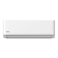
Air Conditioning Indoor Unit
Please refer to Corp1908-L5 for indoor and outdoor unit error codes and component diagnostics.

Table of Contents

Question and Answer IconNeed help?

Do you have a question about the Lennox MWCA018S4-1P and is the answer not in the manual?

Lennox MWCA018S4-1P Specifications

General IconGeneral
BrandLennox
ModelMWCA018S4-1P
CategoryAir Conditioner
LanguageEnglish

Summary

Indoor Units

1.1. Model Number Identification

Explains how to identify indoor unit model numbers.

1.2. Indoor Unit Specifications

Lists technical specifications for indoor units.

1.3. Indoor Unit Dimensions

Provides dimensional drawings and measurements for indoor units.

1.4. Indoor Unit Clearances

Details required clearances around indoor units for installation.

1.5. Indoor Unit Wall Mounts

Shows dimensions and mounting details for indoor unit wall plates.

Indoor/Outdoor Matches

Air Throw Data

Power and Communication Wiring for Systems

4.1. Overview

Provides a general overview of power and communication wiring.

4.2. Wire Gauge

Specifies the required wire gauge for system connections.

4.3. Terminal Connections

Illustrates terminal connections for indoor and outdoor units.

Indoor Unit Diagrams

Wireless Remote

6.1. Requirements

Outlines requirements for using the wireless remote controller.

6.2. Remote Control Specifications

Lists the technical specifications of the wireless remote control.

6.3. Function Buttons

Explains the functions of various buttons on the remote control.

6.4. Display

Describes the remote controller's display icons and their meanings.

6.5. Operations

Details how to operate the system using the wireless remote.

Connection to Centralized Controller

7.1. Set Indoor Unit Address for Centralized Control

Explains how to set the unique address for indoor units using dip switches.

Single Zone Outdoor Units

8.1. Model Number Identification

Explains the model number structure for outdoor units.

8.2. Specifications

Lists technical specifications for single-zone outdoor units.

8.3. Cooling Capacity

Provides cooling capacity data for various indoor/outdoor temperature conditions.

Outdoor Unit Dimensions

Outdoor Unit Clearances

8.5.1. Single Units

Specifies clearance requirements for single outdoor unit installations.

8.5.2. Multiple Units

Details clearance requirements for multiple outdoor unit installations.

Refrigeration Pipe Work

9.1. Single-Zone Refrigerant Cycle Diagram

Illustrates the refrigerant flow diagram for single-zone systems.

9.2. Single-Zone Piping Limitations

Outlines limitations for single-zone refrigerant piping length and elevation.

Outdoor Unit Connections and Line Set Usage

10.1. Pipe Length

Discusses maximum piping length and height difference.

10.2. Torque Requirements

Specifies torque requirements for refrigerant pipe connections.

Power and Communication Wiring for Systems

Outdoor Unit Diagrams

Installation Requirements

13.1. Gas Leak Check with Soap Water:

Describes how to perform a gas leak check using soap water.

13.2. Air and Moisture

Explains the problems caused by air and moisture in the refrigerant system.

13.3. Air Purging using a Vacuum Pump

Step-by-step guide for air purging using a vacuum pump.

13.4. Adding Refrigerant if Pipe Length Exceeds Charge Less Pipe Length

Instructions for adding refrigerant based on pipe length.

13.5. Add Refrigerant after Long-Term System Operation

Procedure for adding refrigerant after the system has operated for a long period.

Electronic Function

14.1. Abbreviation

Lists abbreviations used in electronic function descriptions.

14.2. Electric Control Working Environment.

Specifies the working environment for electric controls.

Adding Refrigerant - Single-Zone Systems

Single-Zone Outdoor Unit LED Locations

Specifications and Operations

17.1. Cooling Chart

Provides cooling capacity data for various temperature conditions.

17.2. Capacity Request Calculations

Explains how to calculate capacity requests based on various factors.

17.3. Outdoor Fan Control

Details how the outdoor fan speed is controlled.

Indoor and Outdoor Unit Disassembly

18.1. Indoor Unit (All Models)

General guide for disassembling indoor units.

18.1.1. Front Panel

Step-by-step instructions for removing the indoor unit's front panel.

18.1.2. Electrical Parts

Instructions for safely removing electrical components from the indoor unit.

18.1.3. Evaporator

Procedure for removing the evaporator from the indoor unit.

18.1.4. Fan Motor and Fan

Instructions for disassembling the fan motor and fan assembly.

18.1.5. Step Motor

Procedure for removing the stepping motor from the indoor unit.

18.1.6. Drain Hose

Instructions for removing the drain hose.

Outdoor Unit

18.2.1. Panel Plate (MWCA009S4, MWCA012S4 and MWCA018S4)

Steps to remove the panel plate for specific outdoor unit models.

18.2.2. Panel Plate (MWCA024S4)

Steps to remove the panel plate for the MWCA024S4 outdoor unit.

18.2.3. Electronic Components (MWCA009S4 and MWCA012S4)

Instructions for disassembling electronic components for specific outdoor units.

18.2.4. Electronic Components (MWCA018S4)

Instructions for disassembling electronic components for the MWCA018S4 outdoor unit.

18.2.5. Electronic Components (MWCA024S4)

Instructions for disassembling electronic components for the MWCA024S4 outdoor unit.

18.2.6. Fan Disassembly (MWCA009S4 and MWCA012S4)

Steps to disassemble the fan for specific outdoor unit models.

18.2.7. Fan Disassembly (MWCA018S4)

Procedure for disassembling the fan for the MWCA018S4 outdoor unit.

18.2.8. Fan Disassembly (MWCA024S4)

Procedure for disassembling the fan for the MWCA024S4 outdoor unit.

18.2.9. Sound Blanket

Instructions for removing the sound blanket.

18.2.10. Compressor

Procedure for removing the compressor, including refrigerant recovery.

Related product manuals