18
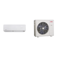
Table 4. Flaring Piping
Pipe Diameter
Flare Dimension
A (mm)
Flare Shape
Min Max
1/4” (6.35) 8.3 8.7
R0.4~0.8
A
45
°
90°
4
-
+
3/8” (9.62) 12.0 12.4
1/2” (9.52” 15.4 15.8
5/8” (15.9) 18.6 19.1
3/4” (22.9) 22.9 23.3
8. After aring the pipe, temporarily sealed pipe ends with
adhesive tape to avoid contaminants from entering
the pipes.
9. The seal on the unit refrigerant piping connections
should remain in place until the last possible moment.
This will prevent dust or water from getting into the
refrigerant piping before it is connected.
10. CAREFULLY adjust refrigerant piping connections to
suit the application.
11. Slowly loosen one of the are nuts to release the
factory nitrogen charge from the indoor units only.
12. Remove the are nuts from the connections on the
unit and discard the seal from each of the piping
connections.
13. Slide the are nuts onto the ends of the eld-provided
refrigerant piping before using a suitable aring tool to
are the end of the copper pipe.
14. Apply recommended HFC-410A refrigerant lubricant
to the outside of the ared refrigerant lines.
IMPORTANT
The compressor in this unit contains PVE
oil (Polyvinylether). PVE oil is formulated for
hydrouorocarbon (HFC) refrigerants, such as HFC-
410A, which this system contains. While it may have
some miscibility properties with mineral-based oil and
POE oil (Polyolester), it is not recommended to mix PVE
oil with any other type of refrigerant oil.
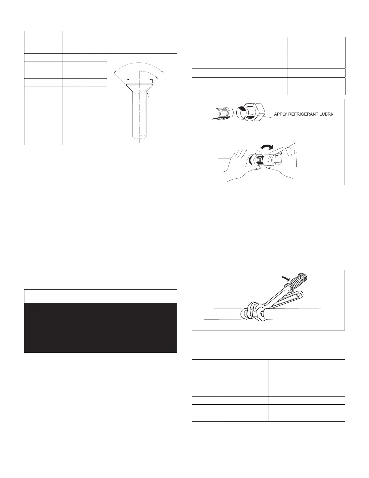
15. Align the threaded connections with the
ared refrigerant lines. Tighten the are nuts
lightly at rst to obtain a smooth match as
illustrated in “Figure 31. Making Connections
(Male to Female Connection)”.
Table 5. Refrigerant Piping and Indoor Unit
Connection Sizes
Size
(Btuh)
Liquid Line
in.
Suction Line
in.
6000, 9000 1/4 3/8
12000 1/4 1/2
18000 1/4 1/2
24000 3/8
5/8
30000 3/8 5/8
A
B
CANT ON THE OUTSIDE OF
THE FLARE
MALE FLARE
CONNECTION
Figure 31. Making Connections
(Male to Female Connection)
16. Once snug, continue another half-turn on each nut
which should create a leak-free joint. A torque wrench
may be used to tighten are nuts using “Table 6. Flare
Nut Torque Recommendations”. Do not over-tighten
a ared joint. Flared connections should always
be accessible and must be insulated to prevent
condensation.
17. After refrigerant piping has been installed and checked
for leaks, apply insulation over all ared connections.
TORQUE WRENCH
TO INDOOR
UNIT
TO OUTDOOR UNIT
BACKUP
WRENCH
Figure 32. Tighten Flare Nut
Table 6. Flare Nut Torque Recommendations
Outside
Diameter
Recommended
Torque
No torque wrench available
Finger tighten and use an
appropriately sized wrench to
turn an additional:
Inches
1/4 15 ft.-lb. (20 N) 1/4 turn
3/8 26 ft.-lb. (35 N) 1/2 turn
1/2 41 ft.-lb. (56 N) 7/8 turn
5/8 48 ft.-lb. (65 N) 1 full turn
 Loading...