Page 8
505,276M 10/09
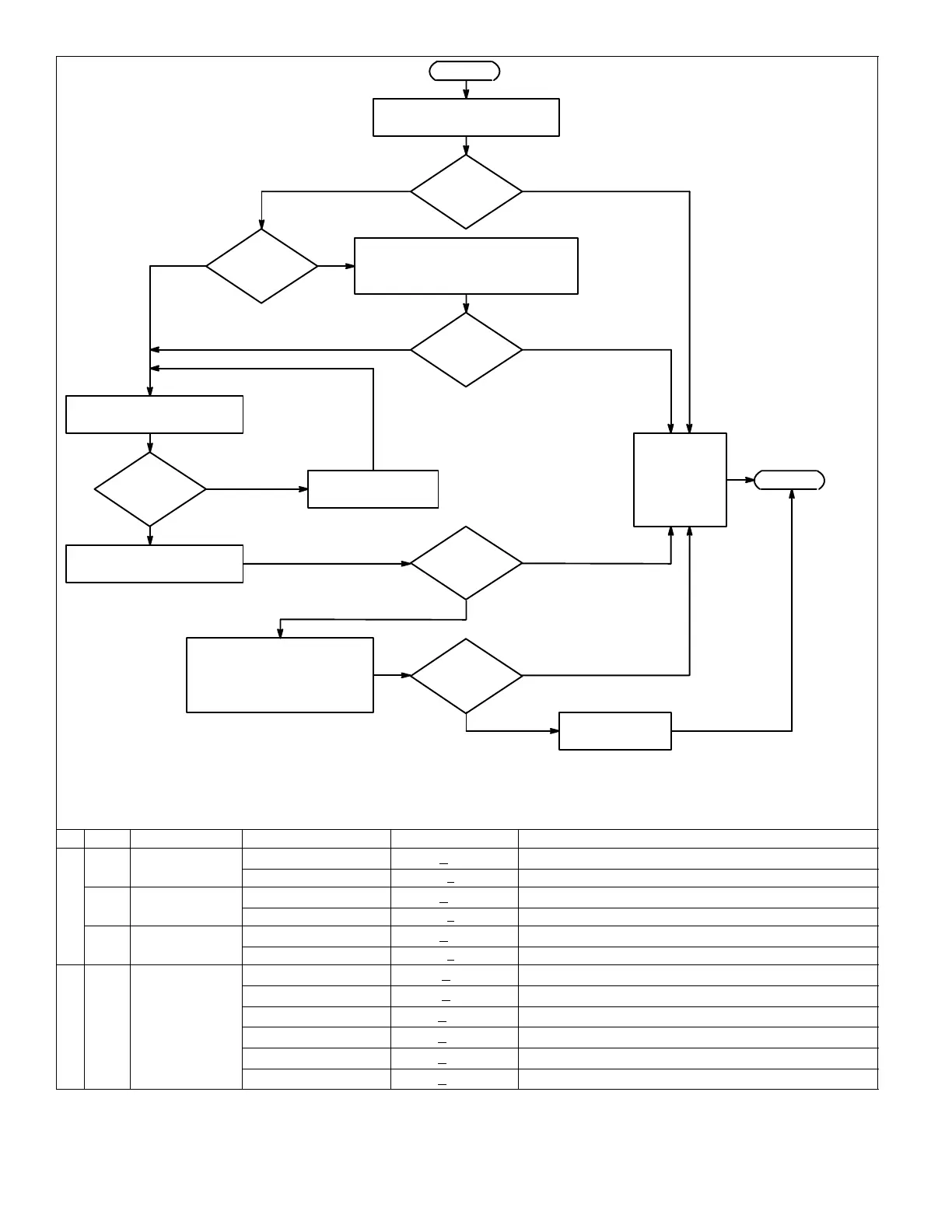
END
YES
NO
Replace control
box assembly.
NO
Check power supply (breakers, plug,
electrical wiring). Repair electrical
problem and plug in power cord.
YESNO
Slide lamp securely
into lamp socket.
YES
NO
Are lamps
seated securely
in sockets?
Continue
with
maintenance
per unit
instruction
manual.
NO
Look through access panel
viewing port to check lamps.
START
NO
Unplug PCO power cord and
immediately plug back in.
Are
lamps
lit?
Voltage Readings for Troubleshooting
All voltages are AC, reference to earth ground (Green wire/terminal), at 75°F. All read-
ings should be taken with lamps securely installed in sockets and circuit connections
made.
SPM = Surge Protection
Module = Part number X8928
YES
YES
Check all electrical
connections, lamps, surge
protector, and ballast. Replace
any burned out or damaged
components and plug unit in.
Is
there power to
PCO?
Are
lamps
lit?
Are
lamps
lit?
Gently pull on lamp to make
sure the lamps are in place.
Did
lamps
light?
YES
STEP INPUT/OUTPUT WIRE/TERM COLOR NORMAL READING SERVICE ACTION (See wiring diagram, Figure 7, Page 5)
BLACK
>105
Replace input power connection or socket if less than 105 VAC.
WHITE <2 Replace SPM if greater than 2VAC.
BLACK
>105
Replace SPM if less than 105VAC.
M
WHITE <2 Replace SPM if greater than 2VAC.
S
BLACK
>105
Replace SPM if less than 105 VAC.
WHITE <2 Replace SPM if greater than 2VAC.
RED
>60
Replace ballast if less than 60VAC.
RED
>60
Replace ballast if less than 60VAC.
T
YELLOW
>110
Replace ballast if less than110VAC.
LA
4 OUTPUT
YELLOW
>110
Replace ballast if less than 110VAC.
AL
BLUE
>200
Replace ballast if less than 200VAC.
BLUE
>200
Replace ballast if less than 200VAC.
Figure 8. Troubleshooting Flow Chart
 Loading...