XP-6515 4/09 13Section 2 Operation
Control or Indicator Item Description
LED display
Runtime hours Displays total generator set runtime hours while the generator set is running and
when no other codes are displayed.
Metering
display
Displays AC voltage (output), frequency, and battery voltage. Press the up or
down arrow when runtime hours are displayed to step through these displays.
Crank indication Displays CC_1, CC_2, or CC_3 to indicate the first, second, or third attempt to
start the engine. The last digit flashes during the crank cycle rest periods.
Software
version number
The software version number (v#.##) is displayed when entering configuration
mode. See the installation manual.
Fault codes Flashes a 2- or 3-letter fault code to indicate various fault conditions. See
Section 2.6.
Keypad Select and
arrow buttons
Use the arrow buttons to step through the data displays. See Figure 2-3.
The keypad is also used for controller setup and adjustment. The setup and
adjustment functions are password-protected. Have setup and adjustments
performed only by a Lennox dealer.
Generator set master
switch
Three-position
switch
Switch functions as the generator set operation and controller reset switch.
Figure 2-2 Controls and Indicators
2.3.2 Controller Keypad
The three buttons on the controller keypad are Select,
Up, and Down.
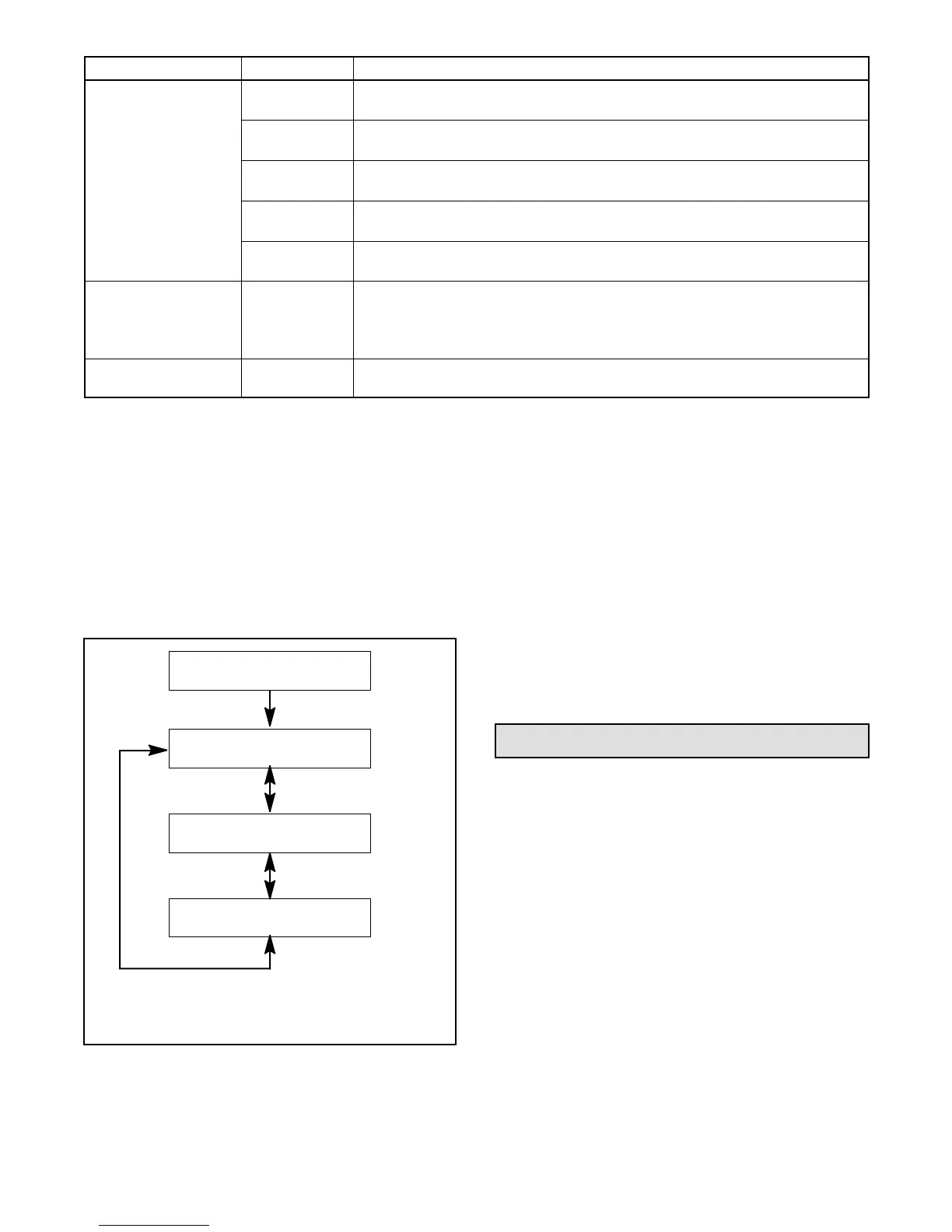
When the generator set is running, the up and down
arrow buttons can be used to step through system data
displays as shown in Figure 2-3. After 10 seconds, the
display returns to engine runtime hours.
1. Generator set master switch in AUTO
2. Step through using up or down arrow buttons
3. After 10 seconds, display returns to runtime hours
tp6515
Engine Runtime
XXX.X hours
Output Voltage
VAC
Output Frequency
Hz
Battery Voltage
VDC
Figure 2-3 Data Displays
The buttons on the controller keypad are also used for
system configuration and adjustment. The system
configuration is factory-set and should not require
changes under normal operating conditions. Contact a
Lennox dealer or service technician if adjustments are
required.
2.3.3 Generat or Set Master Switch
The generator set master switch is located on the
junction box below the user interface. The master
switch positions are RUN, OFF/RESET, and AUTO.
See Section 2.5 for operation instructions.
2.4 Controller Power
The controller is powered by the generator set engine
starting battery.
Note: The generator sets are equipped with factory-
installed battery chargers to prevent battery
discharge. The battery charger must be
connected to utility power.
2.4.1 Standby Mode
When the generator set master switch is in the AUTO
position and the engine is not running, the controller is in
standby mode. Engine runtime hours are shown on the
display. A remote start signal (contact closure) will start
and run the generator set.
The controller can be set to go into sleep mode if there is
no start signal for 48 hours.
 Loading...