Page 28 - IOM / ROOF-TOP FLEXY™ Series
GAS BURNERGAS BURNER
GAS BURNERGAS BURNER
GAS BURNER
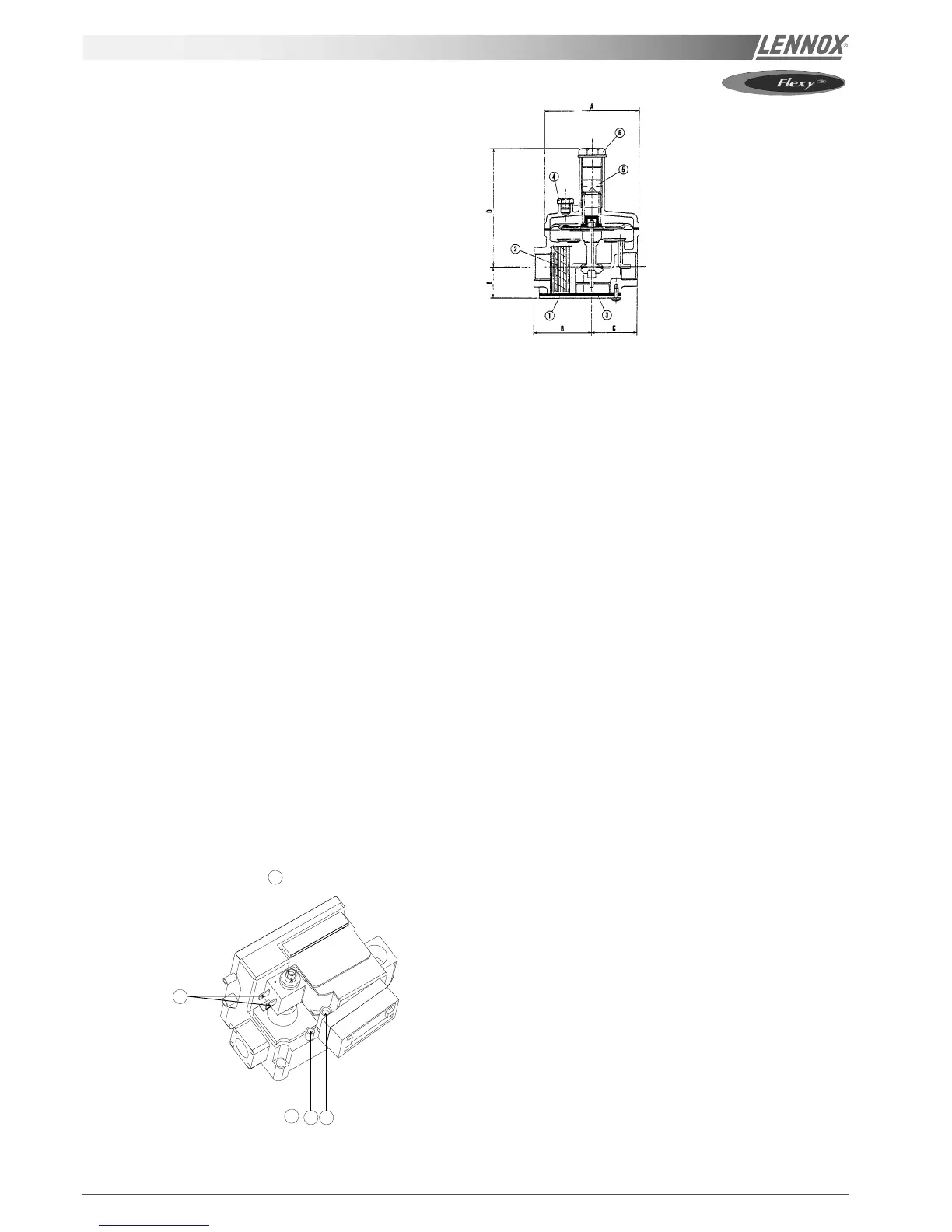
PRESSURE REDUCING VALVE SETTING
- Connect the tube of the manometer to the power
pressure inlet of a solenoid valve (5-figure 24) after
loosening the screw.
- Remove the safety plug of the expansion valve setting.
- Use a screwdriver to pre-set by placing the screw at a
depth of 34 mm.
- Place the burner(s) in operation at maximum power and
set the output pressure. Turn (clockwise) to increase the
pressure and (anticlockwise) to reduce it.
- When the pressure has been set, replace the safety
plug.
- Disconnect the pressure gauge and retighten the screw.
PRESSURE REGULATOR CONTROL OR
SETTING
This is located on the burner tiers (1 – figure 24) of the gas
control assembly.
- Increase the value of set point 1 (temperature set point)
to a temperature higher than room temperature )
(variable 1).
- Wait until the operation of the burner(s) reaches maxi-
mum power.
- Connect the tube of the manometer to the injection
pressure inlet after having loosened the screw (4-figure
24).
- Wait until a stable pressure is displayed on the pressure
gauge.
- Use a 8 mm key to adjust the maximum pressure (3 –
figure 24) – clockwise to increase it and anticlockwise to
reduce it. The maximum pressure must always be set
before setting the minimum pressure.
- The minimum pressure must be measured if the
regulator is not supplied. By disconnecting the tracer
wire 116 on card EF45 or EF46 for the one-ramp module
or the upper ramp of the two-ramp module. It can be
adjusted with a 3.5 mm screwdriver on the screw
located inside the maximum pressure setting.
- For the setting of the second ramp, disconnect the
tracer wire 116 or 126 in order to switch to low speed.
Figure 23
1
2
3
4 5
Pressure taps :
(4) : Injection
(5) : Supply
Figure 24
- Manipulate the regulator several times by connecting
and disconnecting wire 116 or 126 in order to check the
low and high speed settings.
Note : The maximum pressure setting affects the
minimum pressure setting and may have to be changed.
- When the settings are correct, connect wires 116 and
126, making sure they are properly tightened, remove
the pressure gauge and replace the safety cap.
- Restart the unit and watch the burner complete several
full cycles to ensure that all the components are working
properly.
NOTE : The minimum and maximum pressure settings
corresponding to the various gas types are listed in the table
at the end of this manual.
 Loading...