Do you have a question about the Lennox ROOFTOP FLEXY FCA Series and is the answer not in the manual?
Checks to ensure products are in good working order upon receipt.
Recommended procedures for units put into storage for medium to long-term.
Advice on keeping the maintenance key in an accessible place for panel access.
Explanation of the information provided on the unit's rating plate.
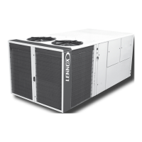
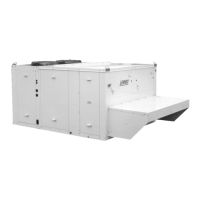
Table detailing the dimensions and weights of various roof-top unit models.
Guidance on how to move the equipment using lifting holes and slings.
Items to check before installing the equipment for proper operation.
Requirements for the installation surface and necessary clearances.
Ensuring pipework is secured, insulated, and avoiding condensation.
Recommendations for correct installation on a roof mounting frame.
Guidance on fitting the unit on corner posts using the provided frame.
Checks required before connecting the unit to the power supply.
Steps for powering up the system with the unit isolating switch.
Guidance on operating and interacting with the CLIMATIC™ system.
Interpreting readings using manometers based on environmental factors.
Performing various safety tests on the unit's components.
Procedure for testing reversible units' cycle functionality.
Procedure for testing and adjusting airflow using pulleys and belts.
Table referencing unit/fan kits for airflow balancing purposes.
Detailed example of airflow balancing calculation and adjustment process.
Specific procedure for balancing airflow on FXA/FXK models.
Understanding error codes related to filters and their meaning.
Instructions for replacing the unit's filters, including removal and installation.
Procedure for connecting the heating coil to isolating valves correctly.
Warning about potential corrosion from electrolytic reaction.
Assembling and installing condensate traps for proper drainage.
Methods to protect the unit's water coils against freezing.
Checks required before commissioning the gas burner.
Explanation of the burner ignition sequence and operation.
Procedure for setting the pressure reducing valve for gas burners.
Adjusting pressure regulator settings for burner tiers.
Checks for the ignition electrode tip condition and correct spacing.
Correct placement of the ionisation sensor within the flame.
Steps for disassembling the gas burner for service and maintenance.
Common problems and solutions for gas burner operation.
Procedure for reassembling the gas burner components after service.
Initial belt tensioning and checks after 50 operating hours.
Conditions and procedure for replacing drive belts.
Steps to safely remove the fan pulley from the shaft.
Procedure for cleaning, installing, and securing the fan pulley.
Steps for installing and removing the pulley motor assembly.
Checking transmission alignment using a ruler after pulley adjustment.
Explanation of the KP17 Comfort control display interface and features.
Requirements for connecting the KP17 remote display using recommended cable.
Identification of components and labels on the KP02 display unit.
Examples of display formats for hour, date, and variable values.
Explanation of the four operating modes of the maintenance display.
Procedures for reading and setting date and time modes.
Procedures for navigating and changing variable and setpoint values.
Procedure for accessing setpoints using a password.
Table listing first-level setpoints with their possible ranges.
Table listing second-level setpoints with their possible ranges.
List of variables with their corresponding numbers for the 1st level.
Explanation of the KP07 display screen keys and their variable functions.
Description of the 5 fixed function keys on the KP07 display.
Mode for changing variable values on the active screen.
Indicates when the machine is powered up.
Indicates when a general fault has been detected.
How to adjust the display contrast in modification mode.
Overview of the KP07 graphic control display screen layout.
Explanation of icons used for keys, sensors, conditions, and errors.
Icons representing different sensors on the display.
Icons representing various operating conditions.
Icons representing different operating statuses.
Icons representing various error codes and fault states.
Description of input functions for BMS connection via hard contacts.
Description of output functions for BMS connection.
How to turn the unit ON or OFF via setpoints or remote control.
Programming operating zones and time slots for daily control.
Details of parameters defined for time slots and their functions.
Adjusting switch time to the morning slot based on thermal inertia.
Power factors for cooling/heating based on temperature difference.
Sequence of component activation for cooling and heating operations.
Maintaining supplied air temperature using setpoint 61.
Power factors for dehumidifying/humidifying based on hygrometry.
Activating air damper regulation using setpoint 66.
Control stages and differentials for dehumidification.
Control of humidity using band percentage and setpoints.
Setting minimum fresh air damper opening percentage.
Calculating fresh air minimum based on CO2 ratio.
Using the economiser register based on air enthalpy.
Anti-short cycle and equalisation of compressor operating times.
Programming cycle inversion for defrosting the outside coil.
References to diagrams for selecting equipment wiring.
Diagram illustrating the unit's power supply circuit.
Wiring diagrams for the CLIMATIC™ controller.
Wiring diagrams for CLIMATIC™ controller outputs.
Wiring diagram for the DAD module.
Wiring diagram for the RS 232 interface connection.
Wiring diagram for the KP07 graphic control display.
Wiring diagram for the GTC system.
List of electrical components and their corresponding references.
Table listing safety and error codes with their descriptions.
Detailed explanations for specific safety and error codes.
Basic checks to perform before seeking technical assistance.
Common operating faults, their causes, and solutions.
Maintenance for motor and fan assembly, including belt tension checks.
Maintenance schedule for filters, including cleaning instructions.
Importance of keeping heat exchangers clean for optimal performance.
Maintenance recommendations for the internal evaporator coil.
Maintenance recommendations for the external condenser coil.
Checks for the hot water coil at the start of the heating season.
Inspection of condensate tray and drain trap for sediment and obstruction.
Annual cleaning and checks for the gas burner and associated parts.
Annual check of electrical terminals for dust and tightness.
Annual inspection of refrigerant circuits and related tasks.
Cleaning and inspection of the equipment casing for corrosion.
Schedule outlining recommended maintenance tasks at different intervals.
General warranty terms, period, and conditions.
10-year warranty for rooftop casing against corrosion.
Clarification on warranty requirements and maintenance contract obligations.
| Gas Heating Efficiency | 80% AFUE |
|---|---|
| Refrigerant | R-410A |
| Stages | Single-stage |
| Heating Type | Gas |
| Voltage | 208/230V or 460V |
| Sound Level | 76 dB |