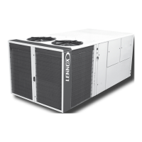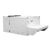
Do you have a question about the Lennox ROOFTOP FLEXY FHK 160 and is the answer not in the manual?
| Model | FHK160 |
|---|---|
| Category | Air Conditioner |
| Refrigerant Type | R-410A |
| Phase | 3 |
| Heating Capacity | 160, 000 BTU/hr |
| Cooling Capacity | 160, 000 BTU/hr |
Essential checks to be completed before proceeding with installation.
Detailed steps for correctly installing the unit on a roof mounting frame.
Pre-power checks for safety, electrical connections, and settings.
Procedures for safely powering up the unit and checking fan rotation.
Performing various safety tests including filter, smoke, and circuit breaker checks.
Procedure for testing and adjusting airflow using pulleys and belts.
Essential checks before commissioning the gas burner system.
Explanation of the burner ignition sequence and related components.
Common issues and troubleshooting steps for the gas burner.
Comprehensive list of adjustable setpoints with their levels and ranges.
List of system variables, their codes, and descriptions.
Detailed explanation of various CLIMATIC™ system parameters.
Diagram illustrating the main power supply connections.
Wiring diagrams for the CLIMATIC™ controller and its components.
List of common error codes and their brief meanings.
Safety system logic for supply air overtemperature and undertemperature.
General faults related to the refrigeration system.
Safety logic for high pressure switches and compressor electrical protection.
General troubleshooting guide for common operating faults.
Troubleshooting steps when the unit is completely non-operational.


