Page 21
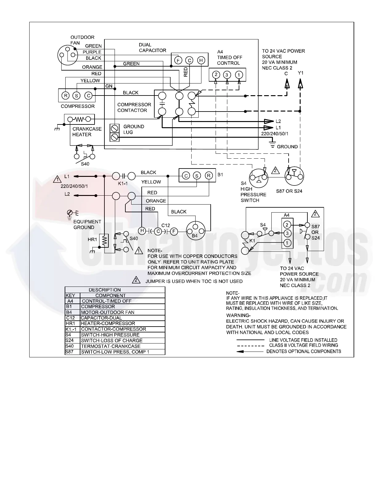
Figure 16.
Typical Field Wiring Diagram T Voltage 220/240v (1PH) 50Hz
NOTE− The thermostat used may be electromechanical or
electronic.
NOTE− Transformer in indoor unit supplies power (24
VAC) to the thermostat and outdoor unit controls.
COOLING:
1. Cooling demand initiates at Y1 in the thermostat.
2. 24VAC from indoor unit (Y1) energizes contactor K1.
3. K1-1 N.O. closes, energizing compressor (B1) and
outdoor fan motor (B4).
END OF COOLING DEMAND:
4. Cooling demand is satisfied. Terminal Y1 is
de-energized.
5. Compressor contactor K1 is de-energized.
6. K1-1 opens and compressor (B1) and outdoor fan
motor (B4) are de-energized and stop immediately.
NOTE− The thermostat used may be electromechanical or
electronic.
 Loading...