24
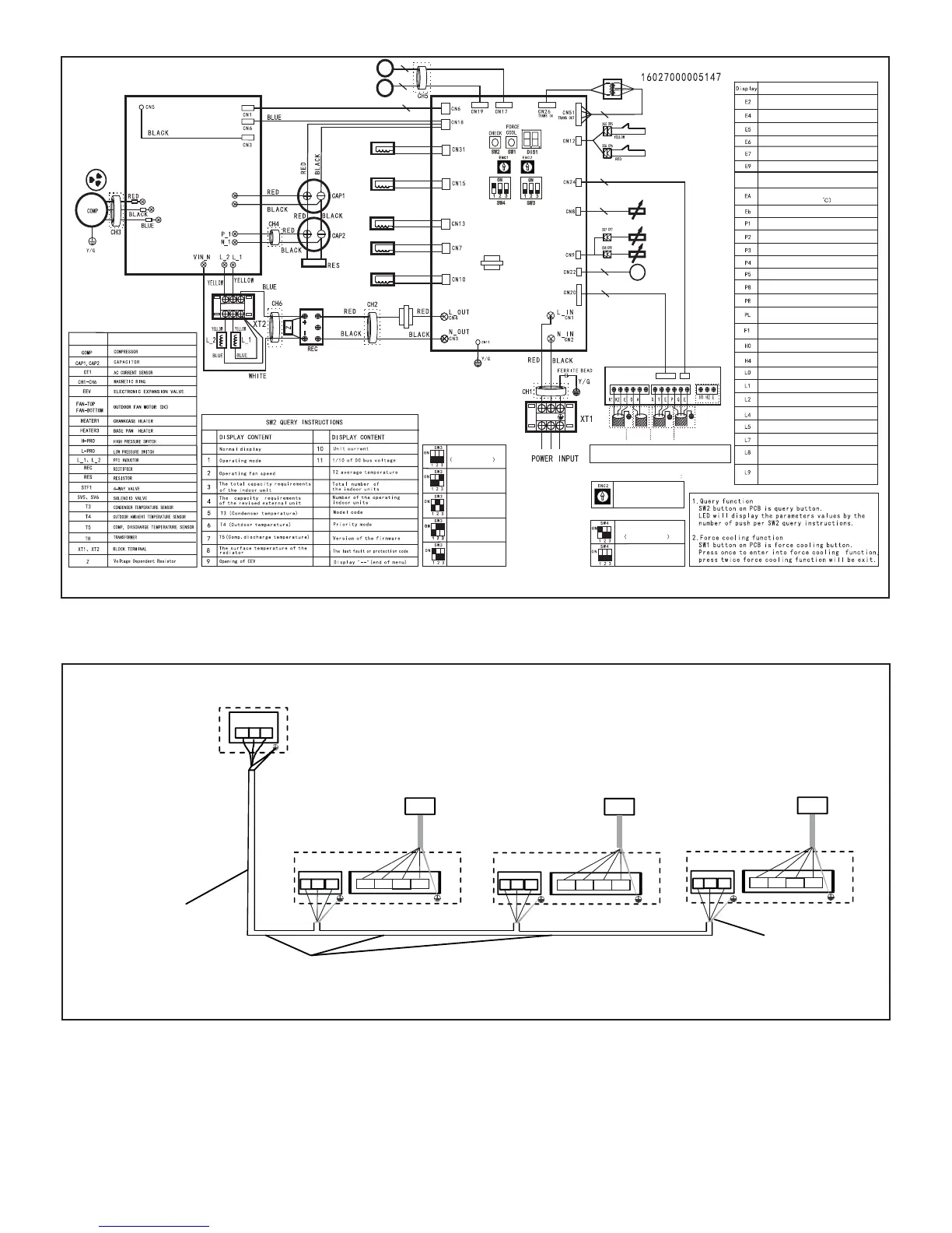
Figure 24. Typical Low-Voltage Field Wiring
18 GA., 3-conductor,
stranded, shielded control wire
(polarity sensitive)
Outdoor unit (heat pump)
Signal wire of
indoor/outdoor units
PQE
Cable Shield
(to ground)
Local
Controller
V0STAT54P-2
Indoor unit
QPE
12V
X
Y
E
Local
Controller
V0STAT51P-2
Indoor unit
QPE
Local
Controller
V0STAT54P-2
Indoor unit
QPE
12V
X
Y
E
12V
X
Y
E
Figure 23. Typical Unit Wiring Diagram
CT1
T5
T3
T4
L2
L1
ORP-H
L-PRO
SV5
BLACK
U
V
W
N
U
V
W
P
TR
STF1
BLUE
A2
A1
A3
1
2
3
4
5
VEE
FAN-BOTTOM
FAN-TOP
3
3
CT1
)TINUROODTUO(MARGAIDGNIRIW
MAIN BOARD
POWER DRIVER
BOARD
Heating priority mode
Factory default
Cooling priority mode
First running
priority mode
Only response to
heating mode
Only response to
cooling mode
GRAY
HEATER1
SV6
0
13
14
15
19
16
18
17
12
NO .
NO .
Low compressor speed
Compressor MCE error
Error Code For Outdoor Unit
Fan output and feedback speed mismatch
Low-pressure switch trip
Hi-pressure switch trip
High compressor discharge temperature
2 times of E6 in 10 minutes
Power voltage out of range
Input current overload
High condenser temperature
Error description
EEPROM error
DC Fan error
High indoor coil temperature
E.9.
Communication error between compressor
module and main board
T3 or T4 errortemperature sensor
Communication error between
indoor unit and outdoor unit
High radiator temperature
(Reserved)
3 times of L0 or L1 in 60 minutes
CODE
PART NAME
Compressor speed difference >15Hz
between adjacent 2 second
Compressor speed difference >15Hz
between the actual and the setting speed
Compressor discharge temperature
sensor error
EEPROM not match main chip
DC fan error more than 5 minutes
in Heat mode (T3>24
DC bus voltage less than 200V for 5S
Compressor module error
DC bus low voltage
DC bus high voltage
Compressor power out of phase
HEATER3
RED
BLACK
CN6
Note : Use a 18 GA., stranded, 3-conductor, shielded
control wire and ensure the shielding layer is grounded.
ToIndoor unit
communication
ToIndoor unit
central controller
Tooutdoor
unit monitor
Communition
connection panel
Topulse meter
Outdoor unit network
address dial-up
Only 0-7 used
ENC2 function definition
SW3 Function Definition:
SW4 Function Definition:
Automatically addressing
CN8
(Reserved)
Factory default
Manually addressing
Typical wiring diagram. Refer to wiring diagram on the unit for actual wiring.
 Loading...