Page 27
XP15 SERIES
mild soap and water solution; rinse thoroughly; allow
filter to dry completely before returning it to the unit or
grille.
NOTE − The filter and all access panels must be in
place any time the unit is in operation.
4. Electronic Air CleanerSome systems are
equipped with an electronic air cleaner, designed to
remove airborne particles from the air passing through
the cleaner. If your system is so equipped, ask your
dealer for maintenance instructions.
5. Indoor UnitThe indoor unit’s evaporator coil is
equipped with a drain pan to collect condensate
formed as your system removes humidity from the
inside air. Have your dealer show you the location of
the drain line and how to check for obstructions. (This
would also apply to an auxiliary drain, if installed.)
IMPORTANT
Sprinklers and soaker hoses should not be installed
where they could cause prolonged exposure to the
outdoor unit by treated water. Prolonged exposure
of the unit to treated water (i.e., sprinkler systems,
soakers, waste water, etc.) will corrode the surface
of steel and aluminum parts and diminish
performance and longevity of the unit.
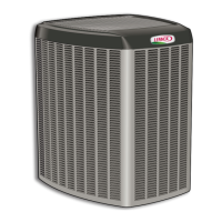
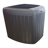
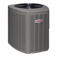
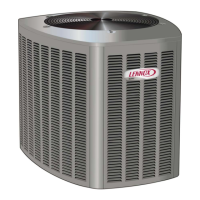
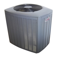
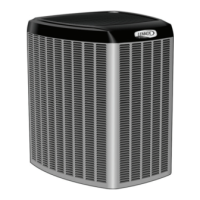
6. Outdoor UnitMake sure no obstructions restrict
airflow to the outdoor unit. Leaves, trash or shrubs
crowding the unit cause the outdoor unit to work harder
and use more energy. Keep shrubbery trimmed away
from the unit and periodically check for debris which
collects around the unit.
When removing debris from around the unit, be aware
of metal edges on parts and screws. Although special
care has been taken to keep exposed edges to a
minimum, physical contact with metal edges and
corners while applying excessive force or rapid motion
can result in personal injury.
Cleaning of the outdoor unit’s coil should be performed
by a trained service technician. Contact your dealer
and set up a schedule (preferably twice a year, but at
least once a year) to inspect and service your heat
pump system.
HEAT PUMP OPERATION
Your new Lennox heat pump has several characteristics
that you should be aware of:
S Heat pumps satisfy heating demand by delivering
large amounts of warm air into the living space. This
is quite different from gas- or oil-fired furnaces or an
electric furnace which deliver lower volumes of
considerably hotter air to heat the space.
S Do not be alarmed if you notice frost on the outdoor coil
in the winter months. Frost develops on the outdoor
coil during the heating cycle when temperatures are
below 45°F (7°C). An electronic control activates a
defrost cycle lasting 5 to 15 minutes at preset intervals
to clear the outdoor coil of the frost.
S During the defrost cycle, you may notice steam rising
from the outdoor unit. This is a normal occurrence. The
thermostat may engage auxiliary heat during the
defrost cycle to satisfy a heating demand; however,
the unit will return to normal operation at the
conclusion of the defrost cycle.
EXTENDED POWER OUTAGE RESTART
PROCEDURE
The heat pump is equipped with a compressor crankcase
heater which protects the compressor from refrigerant
slugging during cold weather operation.
If power to your unit has been interrupted for several hours
or more, set the room thermostat selector to the
emergency heat setting to obtain temporary heat without
the risk of serious damage to the heat pump.
In emergency heat mode, all heating demand is satisfied
by auxiliary heat; heat pump operation is locked out. After a
six-hour compressor crankcase warm-up period, the
thermostat can be switched to the Heat setting and normal
heat pump operation may resume.
THERMOSTAT OPERATION
Though your thermostat may vary somewhat from the
description below, its operation will be similar.
Temperature Setting Levers
Most heat pump thermostats have two temperature
selector levers: one for heating and one for cooling. Set the
levers or dials to the desired temperature setpoints for both
heating and cooling. Avoid frequent temperature
adjustment; turning the unit off and back on before
pressures equalize puts stress on the unit compressor.
Fan Switch
In AUTO or INT (intermittent) mode, the blower operates
only when the thermostat calls for heating or cooling. This
mode is generally preferred when humidity control is a
priority. The ON or CONT mode provides continuous
indoor blower operation, regardless of whether the
compressor or auxiliary heat are operating. This mode is
required when constant air circulation or filtering is desired.
System Switch
Set the system switch for heating, cooling or auto
operation. The auto mode allows the heat pump to
automatically switch from heating mode to cooling mode to
maintain predetermined comfort settings. Many heat
pump thermostats are also equipped with an emergency
heat mode which locks out heat pump operation and
provides temporary heat supplied by the auxiliary heat.
Indicating Light
Most heat pump thermostats have an amber light which
indicates when the heat pump is operating in the
emergency heat mode.
Temperature Indicator
The temperature indicator displays the actual room
temperature.



 To Next Page