Page 19
XP15 SERIES
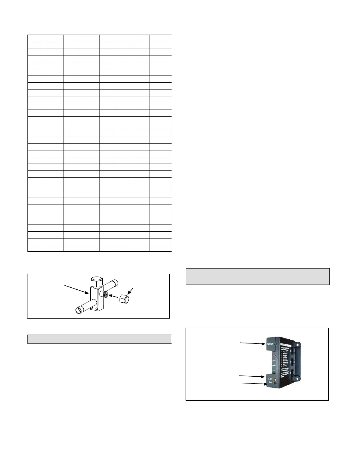
Table 12. HFC−410A Temperature (°F) −
Pressure (Psig)
°F Psig °F Psig °F Psig °F Psig
32 100.8 63 178.5 94 290.8 125 445.9
33 102.9 64 181.6 95 295.1 126 451.8
34 105.0 65 184.3 96 299.4 127 457.6
35 107.1 66 187.7 97 303.8 128 463.5
36 109.2 67 190.9 98 308.2 129 469.5
37 111.4 68 194.1 99 312.7 130 475.6
38 113.6 69 197.3 100 317.2 131 481.6
39 115.8 70 200.6 101 321.8 132 487.8
40 118.0 71 203.9 102 326.4 133 494.0
41 120.3 72 207.2 103 331.0 134 500.2
42 122.6 73 210.6 104 335.7 135 506.5
43 125.0 74 214.0 105 340.5 136 512.9
44 127.3 75 217.4 106 345.3 137 519.3
45 129.7 76 220.9 107 350.1 138 525.8
46 132.2 77 224.4 108 355.0 139 532.4
47 134.6 78 228.0 109 360.0 140 539.0
48 137.1 79 231.6 110 365.0 141 545.6
49 139.6 80 235.3 111 370.0 142 552.3
50 142.2 81 239.0 112 375.1 143 559.1
51 144.8 82 242.7 113 380.2 144 565.9
52 147.4 83 246.5 114 385.4 145 572.8
53 150.1 84 250.3 115 390.7 146 579.8
54 152.8 85 254.1 116 396.0 147 586.8
55 155.5 86 258.0 117 401.3 148 593.8
56 158.2 87 262.0 118 406.7 149 601.0
57 161.0 88 266.0 119 412.2 150 608.1
58 163.9 89 270.0 120 417.7 151 615.4
59 166.7 90 274.1 121 423.2 152 622.7
60 169.6 91 278.2 122 428.8 153 630.1
61 172.6 92 282.3 123 434.5 154 637.5
62 175.4 93 286.5 124 440.2 155 645.0
INSTALLING SERVICE VALVE CAPS
Disconnect gauge set and re−install all service valve caps.
INSTALL CAPS
OUTDOOR UNIT
SERVICE VALVE
Figure 29. Installing Service Valve Port Caps
System Operations
The outdoor unit and indoor blower cycle on demand from
the room thermostat. When the thermostat blower switch
is in the ON position, the indoor blower operates
continuously.
THERMOSTAT OPERATION
Some indoor thermostats incorporate isolating contacts
and an emergency heat function (which includes an amber
indicating light). The thermostat is not included with the
unit and must be purchased separately.
EMERGENCY HEAT (AMBER LIGHT)
An emergency heat function is designed into some room
thermostats. This feature is applicable when isolation of the
outdoor unit is required, or when auxiliary electric heat is
staged by outdoor thermostats. When the room thermostat is
placed in the emergency heat position, the outdoor unit
control circuit is isolated from power and field-provided relays
bypass the outdoor thermostats. An amber indicating light
simultaneously comes on to remind the homeowner that the
unit is operating in the emergency heat mode.
Emergency heat is usually used during an outdoor unit
shutdown, but it should also be used following a power
outage if power has been off for over an hour and the
outdoor temperature is below 50°F (10°C). The system
should be left in the emergency heat mode at least six
hours to allow the crankcase heater sufficient time to
prevent compressor slugging.
HIGH-PRESSURE SWITCH
XP15 units are equipped with a high-pressure switch that
is located in the liquid line to the compressor. The normally
closed SPST auto−reset switch opens at 590 psi.
LOW-PRESSURE SWITCH
XP15 units are equipped with a low-pressure switch that is
located in the vapor line to the compressor. The normally
closed SPST auto−reset switch opens at 25 psi and closes
at 40 psi.
SINGLE-SPEED CONDENSER FAN MOTOR
The XP15 is equipped with a single-speed condenser fan
motor. The compressor contactor and defrost control
board (DCB) controls the operation of the motor.
FILTER DRIER
The unit is equipped with a large−capacity biflow filter drier
which keeps the system clean and dry. If replacement is
necessary, order another of like design and capacity.
Replacement filter driers must be suitable for use with
HFC−410A refrigerant.
Lennox System Operation Monitor
(LSOM)
The LSOM detects the most common fault conditions in
the system. When an abnormal condition is detected, the
LSOM communicates the specific condition through its
ALERT and TRIP lights. The LSOM is capable of detecting
both mechanical and electrical system problems. See
figure 30 for LSOM LED locations.
Figure 30. LSOM
TRIP LED
POWER LED
ALERT LED



 To Next Page