D-71Z-2444 (1.0) 2018-03 4
Montage und Anschluss ♦ Mounting and connection
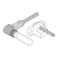
Benannte Teile ♦ Parts named
5
4
1 Messfläche
2 Sensorelemente
(unten: Signalspur,
oben: Referenzspur)
3 Führungsnase
4 Anschlusskabel
5 Montageflansch
6 Abstandslehre
(z. B. 0,2 mm)
1 Measuring surface
2 Sensor elements
(bottom: signal track,
top: reference track)
3 Guide lug
4 Connection cable
5 Mounting flange
6 Distance gauge
(e.g. 0.2 mm)
Bohrbild und Einbaumaße ♦ Hole pattern and installation dimensions
Alle Maße in mm; Allgemeintoleranz ISO 2768-m
All dimensions stated in mm; general tolerance ISO 2768-m
d
b
a
g
90° ± 5.7ʹ
T
Ref
T
Sig
A
A0.01
4 H7 (2 tief/deep)
27
± 0.1
18
7
M 4
r
a
- 1
a Breite der Signalspur: ≥ 4 mm
b Abstand Montagefläche zu Zahnrad:
abhängig von Geometrie des Messzahn-
rads (z.B. Breite der Signalspur)
d Luftspalt: abhängig vom Modul (siehe
technische Daten)
g Breite des Messzahnrads
r
a
=d
a
/2 (mit d
a
= Kopfkreisdurchmesser des
Zahnrads)
T
Ref
Referenzspur
T
Sig
Signalspur
a Width of the signal track: ≥ 4 mm
b Mounting surface to tooth wheel distance:
dependent on the geometry of the target
wheel (e.g. width of the signal track)
d Air gap: dependent on the module (see
technical data)
g Width of the target wheel
r
a
=d
a
/2 (with d
a
= Outside diameter of the
tooth wheel)
T
Ref
Reference track
T
Sig
Signal track
Einbaumaße für Standard-Messzahnräder ♦
Installation dimensions for standard target wheels
Maß ♦
Dimen-
sion
ZA- ZAN ZAZ
g 4 10 10
a
1/2
446
a
N
-44
b 7.5 ± 0.5 7.5 ± 0.5 7.5 ± 0.5
Position der Sensorelemente ♦ Position of the
sensor elements: c
1
= 9.5 mm; c
2
= 6 mm
ZA- ZAN ZAZ
a
1/2
g
a
1/2
a
N
a
N
a
1/2
c
1
c
2
g
g
bb b
c
1
c
2
c
1
Mögliche Einbaufehler ♦ Possible mounting errors
Die Messfläche des MiniCODERs muss sym-
metrisch zum Messzahnrad ausgerichtet wer-
den. Eine unsymmetrische Ausrichtung führt
zu Messfehlern!
The measuring surface on the MiniCODER
must be aligned symmetrically in relation to the
target wheel. Alignment that is not symmetrical
will result in measuring errors!
Amplitudenhöhe Spuren 1/2 ♦ Amplitude tracks 1/2 Offset Spuren 1/2 ♦ Offset tracks 1/2
Amplitudenverhältnis Spur 1/2 zu Referenzspur ♦
Amplitude ratio track 1/2 in relation to reference
track
Nulllage Spur 1/2 zu Referenzspur ♦ Zero position
track 1/2 in relation to reference track
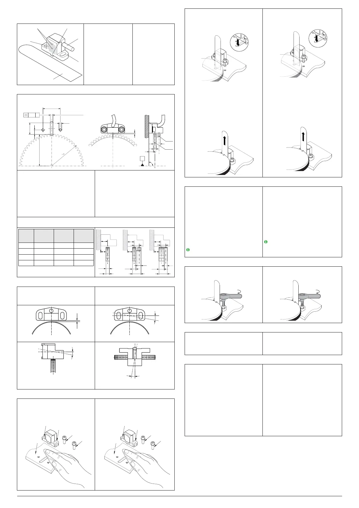
MiniCODER montieren ♦ Mounting MiniCODER
► Übereinstimmung der Moduln von Mini-
CODER und Messzahnrad prüfen.
► Fräsung und Bohrungen in der Aufnah-
mevorrichtung vornehmen.
► Montagefläche und Montageschrauben
reinigen.
► Check the module of the MiniCODER and
target wheel match.
► Mill the recess and make the bores in the
mounting.
► Clean mounting surface and mounting
screws.
► Zwei Schrauben M4 (Empfehlung DIN 912
M4 × 10) mit Schraubensicherung benet-
zen.
► Abstandslehre im Einbauraum auf das
Messzahnrad legen.
► MiniCODER mit den Führungsnasen in die
Führungsnut der Montagefläche einsetzen
und den MiniCODER gegen die
Abstandslehre schieben.
► MiniCODER mit Schrauben, Federringen
und Unterlegscheiben symmetrisch zum
Messzahnrad montieren. Schrauben nur
leicht anziehen.
► Luftspalt mit Hilfe der Abstandslehre
prüfen.
► Abstandslehre entfernen und aufbewahren.
► Wet two screws M4 (recommendation
DIN 912 M4 × 10) using threadlocker.
► Place the distance gauge on the target
wheel in the installation space.
► Fit the guide lugs on the MiniCODER in the
guide slot on the mounting surface and slide
MiniCODER against the distance gauge.
► Mount MiniCODER symmetrically in relation
to the target wheel using screws, spring
washers and washers. Only tighten screws
lightly.
► Check air gap with the aid of the distance
gauge.
► Remove distance gauge and store in a safe
place.
Funktion prüfen ♦ Checking function
Zur Prüfung ein geeignetes Messgerät ver-
wenden (z.B. Oszilloskop).
MiniCODER an das Messgerät an-
schließen.
MiniCODER mit Spannung versorgen.
Messzahnrad langsam drehen und das
Ausgangssignal auf dem Messgerät
beobachten.
Bei korrekter Funktion wird ein einwand-
freies Sinus- oder Rechtecksignal
angezeigt.
Bei Bedarf Phasenlage (Symmetrie) und
Spannungsamplitude (Luftspalt) justieren.
Spannung abschalten und entfernen.
Messgerät entfernen.
Ein zu großer Luftspalt kann zum Verlust
des Messsignals führen.
Use suitable instrument to check (e.g. oscil-
loscope).
Connect MiniCODER to the instrument.
Supply MiniCODER with power.
Slowly rotate target wheel and monitor the
output signal on the instrument.
If function is correct an adequate sine wave
or square-wave signal will be displayed on
the oscilloscope.
If necessary, adjust phase position (symme-
try) and voltage amplitude (air gap).
Switch off power and remove.
Remove instrument.
An excessively large air gap can result in
the loss of the measured signal.
Montage abschließen ♦ Completing mounting
► Montageschrauben mit einem Drehmoment
von max. 2,5 Nm anziehen.
M
► Tighten mounting screws to a torque of max.
2.5 Nm.
M
MiniCODER anschließen ♦ Connecting MiniCODER
MiniCODER entsprechend der
Anschlussausführung korrekt anschließen.
Kabel sicher verlegen und fixieren. Biege-
radius des Kabels und EMV-Hinweise
beachten.
Connect MiniCODER correctly as per the
connection type.
Lay cable securely and fix. Pay attention to
bending radius of the cable and EMC in-
structions.
Störungsbeseitigung ♦ Troubleshooting
Störung: Kein oder fehlerhaftes Ausgangssig-
nal
Abhilfe:
Alle elektrischen Anschlüsse prüfen.
Luftspalt bei allen (klimatischen) Bedingun-
gen für eine volle Zahnradumdrehung
prüfen.
Montageschrauben prüfen.
Prüfen, ob die Messoberfläche oder das
Messzahnrad beschädigt ist. Auswechseln
des beschädigten Bauteils.
Störung: Zählrichtung nicht korrekt
Abhilfe:
Anschlüsse der Spursignale prüfen und
diese gegebenenfalls vertauschen
(Drehrichtungszuordnung).
Malfunction: No output signal or erroneous out-
put signal
Remedy:
Check all electrical connections.
Check air gap in all (climatic) conditions over
a complete tooth wheel revolution.
Check mounting screws.
Check whether measuring surface or the tar-
get wheel is damaged. Replace the dam-
aged component.
Malfunction: Counting direction incorrect
Remedy:
Check connections for the track signals and
change them if necessary (direction of rota-
tion assignment).
 Loading...