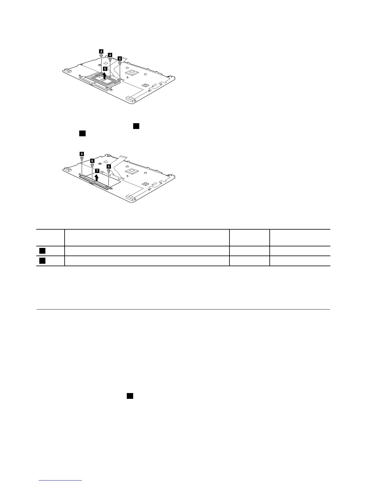
Figure21.Removethetouchpadholder
Step3.Removethethreescrews6,andthenremovethetouchpadbracketinthedirectionshownby
arrow7.
Figure22.Removethetouchpadbracket
Table9.Screwspecifications—removingtheLCDmodule
Screw
label
SpecificationsColor
Torque
4
M2.5×2mm,flat-head,nylon-coated
Black
3.7–4.0kgf-cm
6
M2.5×5mm,flat-head,nylon-coated
Black
3.7–4.0kgf-cm
RefertoTable3“PartnumbersforFRUs(CRUs)”onpage22tolookuptheLenovopartnumbersofthe
followingreplacementparts:
Touchpadmodule
DisassembletheLCDmodule
TheLCDmoduleasawholeisnotaFRU.ItcontainsFRUsasitscomponents.Beforedisassemblingthe
LCDmodule,makesureithasbeendetachedfromthebasecover.Referto“Removethesystemboard
andtheDC-incable”onpage31
forinstructions.
RemovetheLCDbezel
Step1.InsertaprybarbetweenoneinnersideoftheLCDbezelandtheLCDpanelandthencarefully
pulltheLCDbezeloutwards.RepeatthisactionalongtheinneredgesoftheLCDbezeluntilall
hooksthatsecuretheLCDbezelaredetached.
Step2.RemovetheLCDbezel1.
34HardwareMaintenanceManual
 Loading...