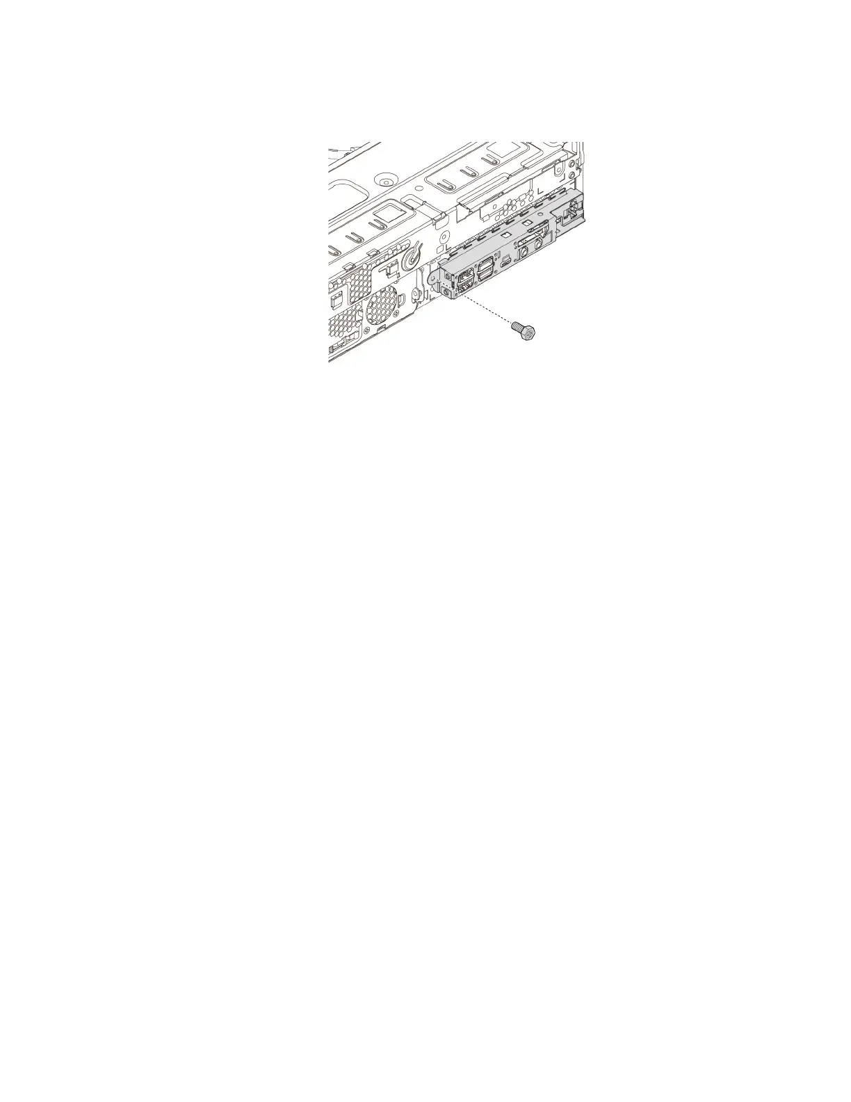
d. Align the screw hole in the front audio and USB assembly with the corresponding hole in the chassis.
Then, install the screw to secure the front audio and USB assembly to the chassis.
Figure 77. Installing the screw
e. Press the release tab and pivot the drive bay assembly outward to open it. See “Preparing your
computer” on page 92.
f. Connect the power button cable to the front-bezel connector on the system board. If the card reader
cable has been disconnected, reconnect it to a USB 2.0 connector on the system board. See “Parts
on the system board” on page 37.
What to do next:
• To work with another piece of hardware, go to the appropriate section.
• To complete the installation or replacement, go to “Completing the parts replacement” on page 154.
ThinkStation LED
Attention: Do not open your computer or attempt any repair before reading and understanding the Chapter
1 “Read this first: Important safety information” on page 1.
To remove or install the ThinkStation LED, do the following:
1. Prepare your computer. See “Preparing your computer” on page 92.
2. Locate the ThinkStation LED. See “Major FRUs and CRUs” on page 34.
3. To remove the ThinkStation LED, do the following:
a. Disconnect the ThinkStation LED cable from the ThinkStation LED connector on the system board.
See “Parts on the system board” on page 37.
Chapter 9. Hardware removal and installation 133
 Loading...
![Preview: Lenovo F0B2 [C20-30]](https://data.easymanua.ls/products/594284/200x200/lenovo-f0b2-c20-30.webp)