18 Information LE1025
way to the chassis or to the rail pickups of the locomotive. Bear in mind that a connection like this is
sometimes made simply when the chassis is put back!
Please contact a service centre if you are in any doubt as to whether all necessary preconditions for
the installation are fulfilled!
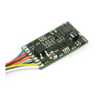
First connect the decoder to the pickups of the locomotive:
• red cable to the pickups which are on the right-hand side of the locomotive in relation to the
direction of travel
• black cable to the pickups which are on the left-hand side of the locomotive in relation to the
direction of travel
Then connect the decoder to the motor connections:
• orange cable to the motor connection previously connected to the right pickups
• grey cable to the motor connection previously connected to the left pickups.
Now connect the functions. Ex-works default settings for the functions are configured as follows:
Function outputs A and B as direction-dependent outputs reacting to F0. This configuration can be
altered as desired.
If you wish to use the function outputs in their initial configuration, connect the outputs as follows:
• function output A (white cable) to the bulb which is at the front in relation to the direction of
travel
• function output B (yellow cable) to the bulb which is at the back in relation to the direction of
travel
If the functions inside the locomotive (e.g. the bulbs of the direction-dependent lights) are not
electrically connected to the chassis (i.e. if they are "potential-free"), connect the other pole of the
function to the blue cable as shown in the illustration. If a connection between functions and chassis
 Loading...