Information LE130XF/LE131XF
Seite 3 von 6 / Page 3 of 6
verwenden möchten, dann verbinden Sie die Ausgänge wie
folgt:
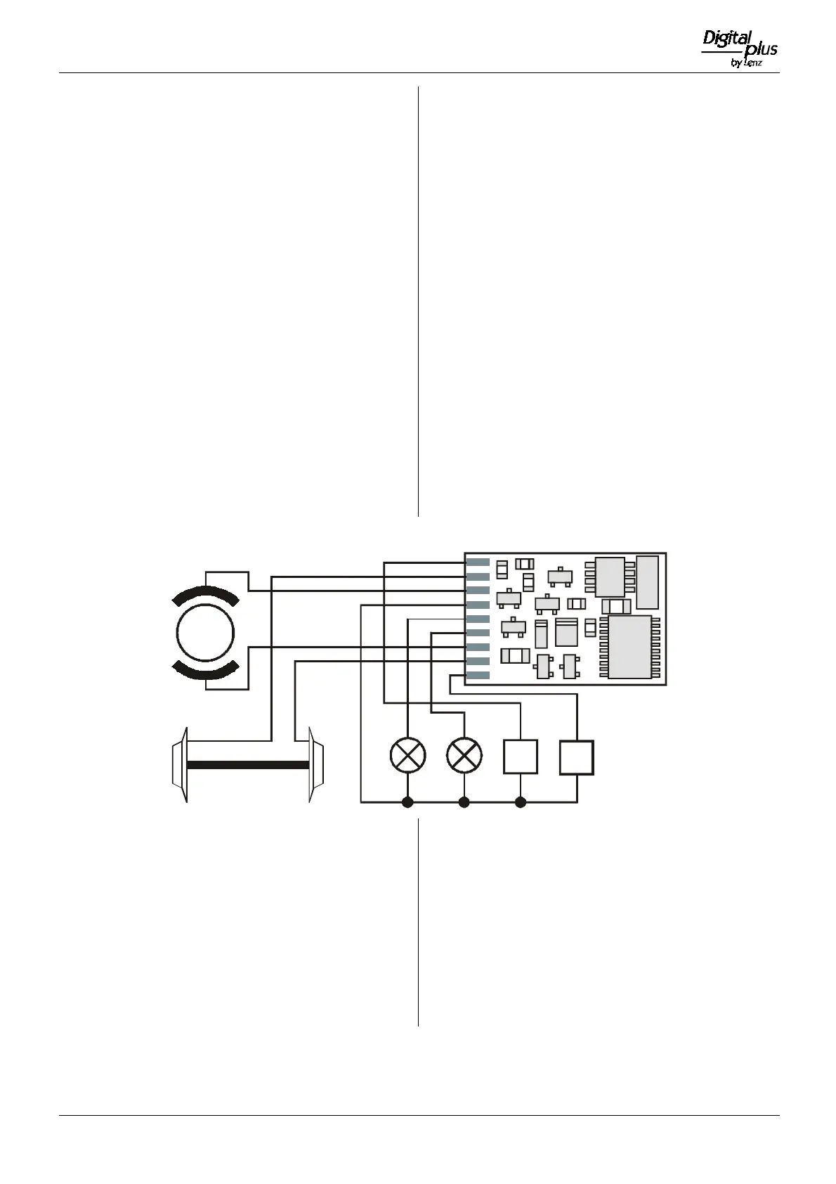
• Funktionsausgang A (weißes Kabel) an das in
Fahrtrichtung vordere Birnchen,
• Funktionsausgang B (gelbes Kabel) an das in
Fahrtrichtung hintere Birnchen.
Sind die Glühbirnchen nicht elektrisch mit dem Chassis der
Lokomotive verbunden (wir nennen diese dann "potentialfrei"),
so schließen Sie nun noch den anderen Pol der Lampen an
das blaue Kabel an, wie in der Abbildung zu sehen. Besteht
eine Verbindung zwischen Glühbirnen und Chassis, so bleibt
das blaue Kabel unbenutzt. Bei Anschluß am blauen Kabel
leuchten die Glühbirnen etwas heller, außerdem funktioniert
dann die richtungsabhängige Beleuchtung auch im Betrieb mit
normalem Gleichstrom. Welche der Varianten Sie umsetzen,
hängt von der Konstruktion der Lokomotive ab.
Für den Anschluß von Leuchtdioden gilt: Blaues Kabel ist
"Pluspol" (Anodenseite der LED), Funktionsausgang ist
"Minuspol" (Kathodenseite der LED). Die Spannung am
Funktionsausgang beträgt ca. 16V.
Schließen Sie nun noch den Funktionsausgang C und D an,
sofern eine weitere Funktion in Ihrer Lok vorhanden ist.
• Funktionsausgang C (grünes Kabel) an eine weitere
Funktion.
• Funktionsausgang D (violettes Kabel) an eine weitere
Funktion.
If you wish to use the function outputs in their initial
configuration then connect the outputs as follows:
• function output A (white cable) to the bulb which in relation
to the direction of travel is at the front
• function output B (yellow cable) to the bulb which in
relation to the direction of travel is at the back
If the functions inside the locomotive (e.g. the bulbs of the
direction dependent lights) are not electrically connected to
the chassis of the locomotive (i.e; if they are, "potential free")
then connect the other pole of the function to the blue cable,
as shown in the illustration. If a connection between functions
and chassis does exist, then the blue cable remains unused.
When connected to the blue cable the bulbs shine somewhat
brighter and, in addition, the direction dependent lighting then
also works in normal DC operation. Which option you choose
depends on the design of the locomotive.
For the connection of LEDs note that the blue cable is the
positive pole (anode side of the LED) and the function output
the negative pole (cathode side of the LED). The voltage at
the function output is approx. 16 V. Please do not forget the
necessary protective resistor.
Now connect the outputs C and D (if your locomotive has
further functions):
• function output C (green cable) to another locomotive
function.
• function output D (purple cable) to a another locomotive
function.
Motor
Schwarz
Black
Orange
Grau
Grey
Rot
Red
Weiß
White
Gelb
Yellow
Grün
Green
Purple
Blau
Blue
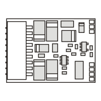
Einbau des LE131XF
Der Schnittstellenstecker gemäß NEM 652 und NMRA.
ermöglicht einen schnellen und problemlosen Umbau von
Lokomotiven.
Ziehen Sie den Brückenstecker von der Schnittstelle der
Lokomotive ab. Bewahren Sie diesen Stecker sorgfältig auf.
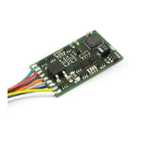
Stecken Sie nun den Stecker des Lokempfängers so auf die
Schnittstelle auf, daß Stift 1 an der aus der Betriebsanleitung
der Lok zu erkennenden Stelle zu liegen kommt. Die Lage des
Kontakt 1 des Steckers erkennen Sie am orangen Kabel.
Achten Sie darauf, daß Sie beim Einstecken keinen der
Steckerstifte verbiegen oder gar abbrechen
Installation of the LE131XF
These decoders come with a NEM652 / NMRA RP-9.1.1
medium plug.This plug makes installation of these decoders
very simple.
To install the decoder simply remove the dummy socket in
your locomotive and install the decoder plug. To ensure the
headlights work properly you must align the plug properly. Pin
1 of the plug connects to the orange wire. Ensure this is
aligned to pin one of the locomotive. If the plug is installed
backwards the lights will not work.
Be careful when installing the plug so that the pins will not be
bent or broken.
 Loading...