24 SF01U
NOTE
• Program the PRESET SPEEDS (Parameters 31-37) to the desired
values.
• PRESET SPEED #2 (04), and TB-13C (Parameter 12) to PRESET SPEED
#3 (04). To select a preset speed, close the appropriate TB-13 terminal(s)
to TB-2 (refer to Parameters 31-37 for the Preset Speed Activation
table).
• If reverse rotation is also required, TB-13A cannot be used as a PRESET
SPEED SELECT. TB-13A must be programmed to select RUN REVERSE
(05) or START REVERSE (06), leaving only TB-13B and TB-13C to select
preset speeds.
• For speed pot control, program Parameter 05 - STANDARD SPEED
SOURCE for 0-10 VDC (03). If none of the preset speeds are selected
(all of the TB-13 terminals are open), the drive will respond to the speed
pot.
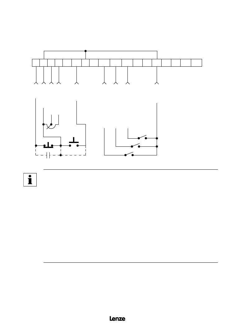
11.5 SPEED POT AND PRESET SPEED CONTROL
Shown below is the wiring for SPEED POT and/or PRESET SPEED control, and either a
two-wire or three-wire start/stop circuit:
1 2
5 6
12
TXA TXB
2 13A 13B 13C14 15 2
STOP
COMMON
0-10 VDC INPUT
START
PRESET SPEED SELECT
COMMON
11 25 31
30
10 VDC SUPPLY
2.5k - 10kΩ
PRESET SPEED SELECT
PRESET SPEED SELECT
The TB-2 terminals are internally connected to each other
Artisan Technology Group - Quality Instrumentation ... Guaranteed | (888) 88-SOURCE | www.artisantg.com
 Loading...