Mechanical installation
Mounting
Mounting of motors on gearboxes with mounting flange
4
16
BA 12.0028−EN 6.0
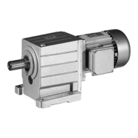
Worm gearboxes
B5 flange
B14 flange
K12.0542/2
Fig. 2 Worm gearboxes prepared for mounting on standard motors, type 52.4 and 52.5
1 Clamping screw
2 Motor key
1. Assemble motor key (2).
2. Push coupling hub onto the motor shaft, observe dimension m.
3. Secure coupling hub against axial movement using the clamping screw (1).
4. Lay spider into the coupling claw at the gearbox side.
5. Align claws of the motor−side coupling hub with its counterpart.
6. Slowly push motor, and bolt onto the gearbox flange.
Motor frame size
Motor shaft Flange dimensions Assembly dimensions
d [mm] l [mm ] a [mm] m [mm]
063 11 23 90 25
063 11 23 140 30
071 14 30 105/140/160 30
080 19 40 120/160/200 40
 Loading...