Do you have a question about the Lenze 9200 Series and is the answer not in the manual?
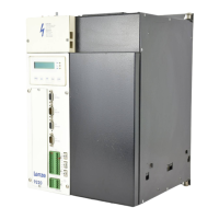
Lists key features of the 9200 controller series.
Provides detailed specifications and ratings for the modules.
Covers enclosure, noise immunity, and environmental specifications.
Details rated data for supply and axis modules.
Specifies electrical ratings for supply modules.
Specifies electrical ratings for axis modules.
Shows physical dimensions of the units.
Lists included items and accessories in the delivery package.
Describes intended use for control cabinets in industrial settings.
Certifies controllers as components, not machines, per directives.
Guides on physical mounting and spacing of units.
Details wiring requirements and safety for electrical connections.
Explains DC-bus capacity rules for multi-axis configurations.
Provides instructions for EMC compliance via proper grounding and screening.
Outlines standards and methods for reducing radio interference.
Covers mains and motor connection details.
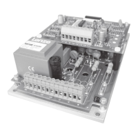
Shows wiring for power supply and motor.
Explains connection and disconnection of external brake resistors.
Details control signal connections for the supply module.
Details thermal contact access for overload protection.
Describes signals for mains status and failure detection.
Explains status signals transmitted between modules via the state bus.
Details control signal connections for the axis module.
Shows pin assignment for the axis module's control terminal block.
Details analog signal selection for set values and monitor outputs.
Explains the function of digital I/O signals and their wiring.
Demonstrates using the module for easy positioning tasks.
Illustrates wiring diagrams for SX-1 positioning control.
Shows a wiring diagram for mains supply connection.
Provides a wiring diagram for a 230V control circuit.
Presents a wiring diagram for a 24V control circuit.
Illustrates control connections for the 9200 series with SX1.
Shows detailed control connections for SX1.
Describes external resistors for increased brake power.
Lists mains chokes for radio interference suppression.
Details RFI filters for radio interference suppression.
Specifies external fuses for semiconductor protection.
Lists various system cables for module connectivity.
Provides cable part numbers for terminal block X5.
Lists cables for frequency selection and encoder output.
Lists system cables for connecting resolvers.
Provides cable part numbers for servo motor power supply.
Lists cables for fan and brake supply.
Presents technical data for asynchronous servo motors.
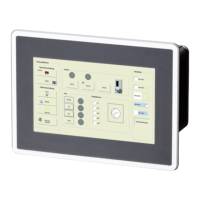
Explains the function of the LCD display and its indicators.
Describes the operations of the control panel keys.
Details the format and content of the LCD text display.
Introduces parameter codes and their selection methods.
Explains methods for changing parameter values.
Guides on permanently saving parameter settings.
Describes how to load saved parameter sets.
Provides step-by-step examples for parameter setting.
Covers initial parameter setup and fault checks before operation.
Overview of monitoring functions and status indicators.
Monitors master frequency increments without activating pulse inhibit.
Monitors DC bus voltage and axis modules during pulse inhibit.
Monitors critical conditions like short circuits and earth faults.
Details specific fault codes including overload, overvoltage, and system faults.
| Category | Controller |
|---|---|
| Protection Class | IP20 |
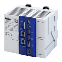
| Series | 9200 |
| Communication | Ethernet, CANopen, Profibus |
| Operating Temperature | 0 to 50 °C |
| Storage Temperature | -25°C to +70°C |
| Relative Humidity | 5% to 95% (non-condensing) |
| PLC Functionality | Integrated PLC functionality |