Electrical installation
Design as isolation
EDKMF2176X DE/EN/FR 4.2
17
H1_E_INST-2176_service_BL
Design as isolation
Function
The CAN repeater automatically separates from a segment if the segment shows a
permanent disturbance level of +1 V ... +5 V between CAN-HI and CAN-LO. The
corresponding red LED is on. The other segment goes on working.
If the permanent disturbance level has disappeared, the segment is connected to the
system again through the CAN repeater.
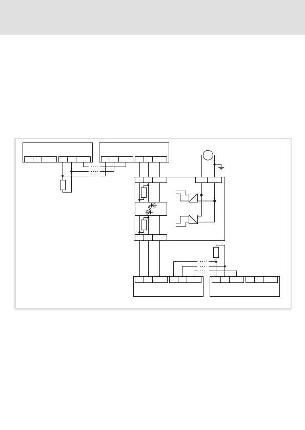
Basic circuit diagram
HI
HI
LO
LO
GND
GND
HI
HI
LO
LO
GND
GND
CAN 2.1
CAN 1.1
HI
HI
LO
LO
GND
GND
HI
HI
LO
LO
GND
GND
CAN 2.n
CAN 1.n
+24VDC
(+9 ... +35 V DC)
CAN2
CAN1
2176
+24
GND
HI
LO
GND
HI
LO
GND
120
120
=
120
120
2176_002
CAN 1.1 … CAN 1.n Nodes in segment CAN1
CAN 2.1 … CAN 2.n Nodes in segment CAN2
A total of max. 63 nodes possible
 Loading...