Electrical installation
Design as service interface
EDKMF2176X DE/EN/FR 4.2
18
H1_E_INST-2176_service_BL
Design as service interface
Function
Via the PC you are able to monitor the system during operation, e.g. with the Global Drive
Control program (GDC).
Note!
ƒ The connection of the PC system bus module is described in the Mounting
Instructions supplied with the module.
ƒ Note the baud rate set in the system on the CAN repeater. This helps to
avoid bus failures and facilitates the work of the service personnel.
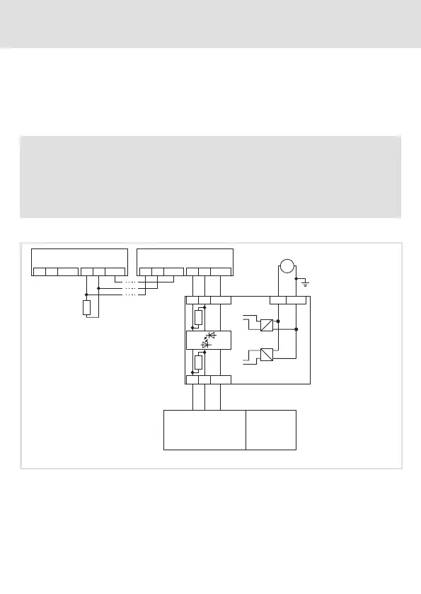
Basic circuit diagram
HI
LO
GND HI
LO
GND
CAN 2.1
HI
LO
GND
HI
LO
GND
CAN 2.n
+24VDC
(+9 ... +35 V DC)
CAN2
CAN1
2176
+24
GND
HI
LO
GND
HI
LO
GND
120
120
=
120
2173-V003
PC
2176_003
2173-V003 PC system bus module 2173, version V003 (with electrical isolation)
PC PC with PS/2 connection
CAN 2.1 … CAN 2.n Nodes in the s egment CAN2, max. 63 nodes possible
 Loading...