Sequential circuit
15
Application examples
15.7
L
15.7-2
EDS82EV903-1.0-11/2002
P r e s s u r e s e n s o r
R e l a y K 1
E x t e r n a l
c i r c u i t
8 2 0 0
M a i n s
C o m p r e s s o r 1
C o m p r e s s o r 2
K 1 1
K 1 2
K 1 4
A c t . p r e s s u r e v a l u e 0 . . . 1 0 V
K 1
X 1
X 3
6 2 7
8
9
7 2 0
2 8
E 1
E 2 E 3 E 4 A 13 9
5 9
S t a n d a r d I / O
G N D 1
G N D 1 G N D 2
A c t . p r e s s u r e v a l u e
0 . . . 1 0 V
S t a r t / s t o p
2 4 V
e x t e r n a l
+
K 3
K 3
K 1 T
K 2
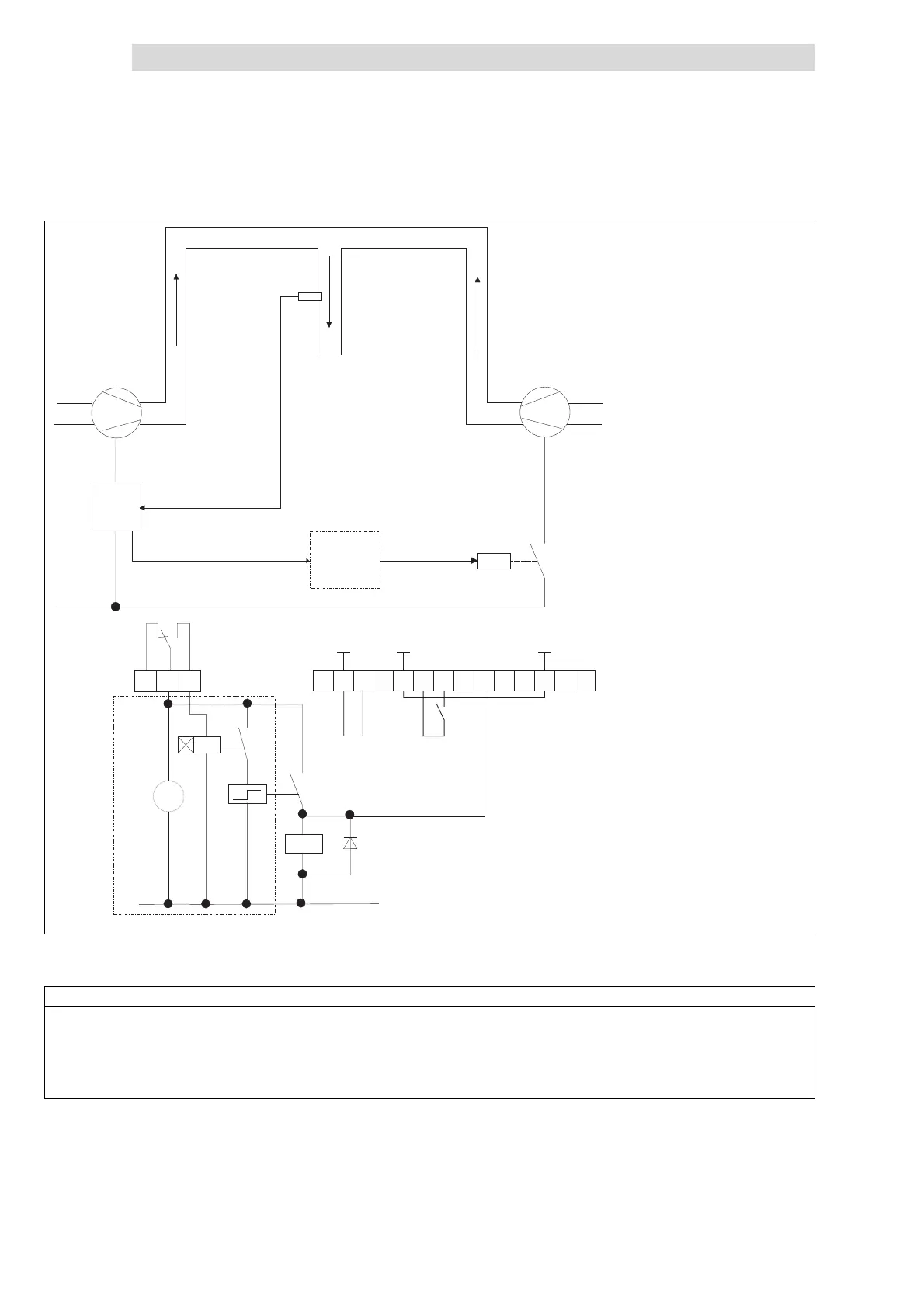
Fig. 15.7-1 Principle of sequential circuits
8200 8200 motec or 8200 vector
Function description for Fig. 15.7-1
1. Activate the threshold 45 Hz K1 in PAR1.
2. If K1 remains picked up, K 2 is conne cted.
3. Compressor 2 is connect ed via K3. At the same time the parameter set is changed via X3/E2 (process controller is not affected)-
4. K1 picks up when the minimum frequency is reached (depending on load). After time K1T is over, K2 picks up again.
5. Compressor 2 is switched off. The parameter set is changed backed to PAR1.
• K1T debounces the switching point of compressor 2 (adapt delay time to process).