Do you have a question about the Lenze M55BH063S04 and is the answer not in the manual?
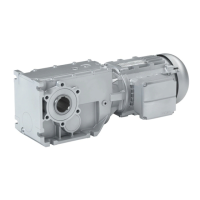
This document provides comprehensive mounting and switch-on instructions for Lenze IE2 and IE3 bevel geared motors, specifically models g500-B, m550-H Version B, and m550-P Version B. It is intended for skilled personnel involved in the electrical and mechanical installation and commissioning of these products.
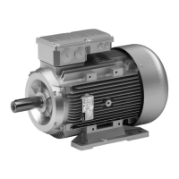
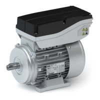
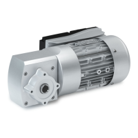
The Lenze geared motors are professional equipment designed for use in trades, specific professions, or industry. They are suitable for operation on the mains or with an inverter. The product consists of a motor and a gearbox, designed to provide specific output torque and speed for various applications. The document details the identification of products through nameplates and product codes, which specify gearbox type, output torque, type of construction, shaft type, housing type, flange mounting, number of stages, motor mounting, and drive size. Motor product codes further specify efficiency class (IE2 or IE3), size, overall length, number of poles, degree of protection (IP54/IP55, IP65/IP66), cooling type (self-ventilation or forced ventilation), brake type (without or spring-applied), feedback options (absolute value encoder, incremental encoder, resolver), and approvals (CE, CCC, cULus, CURus).
The geared motors can be equipped with various extensions, including different types of connectors for electrical installation (terminal box, ICN, M12, HAN), and optional components like oil compensation reservoirs for specific mounting positions.
Efficiency Classes:
Degree of Protection:
Temperature Class:
Permissible Voltage:
Climate Conditions:
Site Altitude:
Air Humidity:
Motor Data (Examples for 50 Hz, 230V/400V):
Electrical Connections:
Mounting Positions: The geared motors support six mounting positions (M1 to M6), indicated on the nameplate. The lubricant amount and gearbox ventilation are adapted to the specific mounting position to prevent damage.
Ventilation: Gearboxes from G50BB145 onwards are supplied with breather elements. For smaller gearboxes (G50AB045 to BB124), no venting measures are required, though the G50BB124 can optionally be equipped with breather elements. Transport locking devices on vent valves must be removed before commissioning.
Hollow Shaft and Shrink Disc: For hollow shaft versions, specific instructions are provided for mounting the machine shaft, including cleaning, loosening clamping screws, pushing the gearbox onto the shaft, and tightening screws in multiple passes. A shrink disc cover is provided for protection against accidental contact.
Torque Plate Mounting: Instructions emphasize supporting the socket of the torque plate at both ends, checking axial clearance, and transferring force at right angles to the torque plate for knee lever designs.
Manual Release Lever: For brakes, a lockable manual release lever can be assembled for service work. It is crucial not to lock the manual release in the service position during operation to avoid brake damage.
Electrical Installation: Detailed connection diagrams are provided for power, brake, feedback, temperature monitoring, and blower connections via terminal box, ICN, M12, and HAN connectors. EMC-compliant wiring is essential and detailed in separate inverter documentation.
Maintenance Intervals:
Lubrication:
Spring-Applied Brake Maintenance:
Safety: All maintenance work must be performed by qualified personnel on de-energized drives, after surfaces have cooled down, and with loads secured. Safety functions related to brakes and feedback systems require professional execution to avoid loss of safety functions.