Do you have a question about the Leroy-Somer VARMECA 32T and is the answer not in the manual?
General safety considerations and personnel qualifications.
Guidelines for the intended use and compliance with directives.
Instructions for safe transportation, storage, and handling.
Requirements for installation and cooling of the equipment.
Safety specifications for electrical connections and wiring.
Safety measures and precautions during operation.
Reference to manufacturer's documentation for servicing.
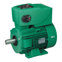
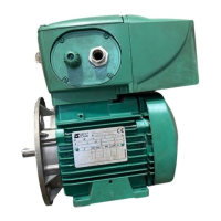
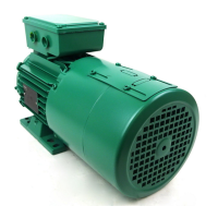
Explanation of the VARMECA 30's integrated motor and drive system.
Listing of VARMECA 30 models based on power supply and rating.
Detailed electrical data, characteristics, and functions of the VARMECA 30.
Specifications for protection index, temperature, altitude, and humidity.
Information on RF interference generated by variable speed drives.
Emission standards conformity for the VARMECA 30.
Immunity standards conformity for the VARMECA 30.
Factors affecting earth leakage current and RCD usage.
Methods to increase control cable immunity.
Precautions for overvoltage in control circuits.
User responsibilities and information on cables and protection devices.
Details on UL conformity for mains supply, cables, and fuses.
Table showing weights and dimensions for different VARMECA 30 types.
Information on fitting the VARMECA 30 motor and ventilation.
Precautions for remote control and shielded cables.
Details on control terminal blocks and their functions.
Terminal blocks for power supply and braking resistors.
Connectors for options like RS485, fieldbus, and encoders.
RS485 connector for console or PC connection.
Connector for encoder feedback module.
Connector for fieldbus modules.
Connector for various options and brake control.
Connection diagrams for standard configurations.
Wiring diagram for the standard VARMECA 31/32 and 33/34.
Wiring diagrams illustrating safety input usage.
Details on using the safety input for locking the drive.
Diagrams for 3-phase supply with safety input, category 1.
Diagrams for 3-phase supply with safety input, category 2/3.
Power supply and control for built-in brake motors.
Power supply for fixed control brake (SO VMA option).
Power supply for sequential control brake (ESFR option).
Using an external source for brake power supply.
Table showing rectified brake voltage based on mains supply.
Examples of wiring two motors in parallel with a single VARMECA.
Ensuring VARMECA is sized for total motor power rating.
Wiring the second motor to specific terminals.
How to connect the brake on the second motor.
Wiring diagrams for SO VMA and VMA ESFR options.
Wiring diagram for the SO VMA 31/32 option.
Wiring diagram for the ESFR 31/32 option.
Connection diagram for the VMA ESFR 33/34 option.
Steps for starting the VARMECA 30 after power supply connection.
How the motor starts automatically when enabled.
Starting the motor using a remote volt-free contact.
Local control of start/stop using specific options.
Methods for setting the motor speed.
Adjusting speed using external voltage or current signals.
Setting speed with control knobs or potentiometers.
Using internal potentiometers for speed adjustment.
Routine care and cleaning instructions for the VARMECA 30.
Procedures for measuring motor current and related parameters.
Notes on measuring input voltages and motor current.
Procedure for measuring motor current when wire loop is inaccessible.
Using the speed control knob with indicator lamps.
Using the control knob with integrated run-stop functionality.
Control knob with forward/reverse/stop and indicator lamps.
Internal speed control using potentiometers.
Details on IP 65 braking resistor options and their specifications.
Information on IP 20 external braking resistor options.
Power supply and control for SO VMA 31/32 brake option.
I/O interface and sequential brake control for ESFR VMA 31/32.
I/O interface and sequential brake control for ESFR VMA 33/34.
Supported fieldbus protocols for interface cards.
Details on the encoder feedback option.
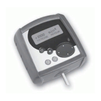
Using the PX LCD console for drive parameter access.
Accessing drive settings via PC software.
Features of the VARMECA 30 operator display.
Using XPress Key for parameter copying and transfer.
General information about the XPress Key function.
Procedure for setting drive parameters using XPress Key.
Information on EMC filters for VARMECA 33/34 drives.
Details on the FLT VMA 31M EMC filter option.
Details on the FLT VMA 31/32 EMC filter option.
| Brand | Leroy-Somer |
|---|---|
| Model | VARMECA 32T |
| Category | Engine |
| Language | English |