Do you have a question about the Leroy-Somer VARMECA 30 and is the answer not in the manual?
General safety precautions, personnel qualifications, and transport/handling instructions.
Guidelines for integrating VARMECA 30 into machines, compliance with directives, and safety devices.
Instructions for correct transportation, storage, and observance of climatic conditions.
Proper installation, cooling, and handling to avoid damage and electrostatic discharge.
Adherence to national specifications, EMC compatibility, and connection guidelines.
Safety devices, capacitor charge warnings, and keeping covers closed during operation.
Reference to manufacturer's documentation for servicing and maintenance.
Explains how the manual guides parameter setting via LCD KEYPAD or VMA SOFT software.
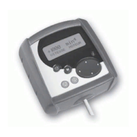
Details the 'LCD KEYPAD micro console' and 'VMA SOFT' PC software options.
Provides physical dimensions of the LCD KEYPAD micro console in millimeters.
Instructions for checking the LCD KEYPAD micro console upon receipt and its connection.
Overview of the LCD keypad's display, buttons, and their functions for operation and settings.
Procedure to select the display language (French or English) when the console powers up.
Lists parameters viewable in read mode for supervision and diagnostics, including motor status.
Step-by-step guide for modifying numerical and mnemonic parameters using the keypad.
Procedure to exit parameter-setting mode and return to read mode using the 'M' button.
Details basic parameters like MINIMUM LIMIT, MAXIMUM LIMIT, and ACCELERATION RAMP.
Parameter for setting the motor's on-load speed, with caution for high inertia applications.
Parameter for the rated voltage indicated on the motor nameplate.
Parameter for power factor measurement, with options for autocalibration or manual entry.
Sets access levels (Read only, Level 1, Level 2) for menu parameters.
Wiring diagram and parameter details for the STANDARD configuration.
Details parameters for sequential brake control, including release and apply thresholds and times.
Configures ADI1 input for various signal types and detection modes.
Configures ADI2 input for various signal types, including PTC sensors.
Sets the proportional gain for the PID control loop.
Sets the integral gain for the PID control loop.
Sets the derivative gain for the PID control loop.
Defines the upper limit for the PID output value.
Defines the lower limit for the PID output value.
Scales the PID output value.
Scales the input value from ADI2.
Sets a preset reference value for PID control.
Sets a preset reference value for PID control.
Displays the calculated error in the PID control loop.
Displays the current output value of the PID control loop.
Table mapping DI4 and DI01 inputs to reference selections.
Configures ADI1 input for various signal types and detection modes.
Sets Preset Reference 2 value.
Sets Preset Reference 3 value.
Sets Preset Reference 4 value.
Table mapping DI4 and DI01 inputs to reference selections.
Details parameters for sequential brake control, including release and apply thresholds and times.
Table mapping DI4, ADI1, DI01 to preset reference selections.
Sets Preset Reference 1 value.
Sets Preset Reference 2 value.
Sets Preset Reference 3 value.
Sets Preset Reference 4 value.
Sets Preset Reference 5 value.
Sets Preset Reference 6 value.
Sets Preset Reference 7 value.
Sets Preset Reference 8 value.
Configures ADI1 input for various signal types and detection modes.
Adjusts the trim percentage for reference correction.
Displays the current analogue reference input value.
Shows the selected reference type and its value.
Table mapping ADI2 to preset reference selections.
Configures digital input for preset speed selection.
Adjusts the trim percentage for reference correction.
Sets Preset Reference 1 value.
Sets Preset Reference 2 value.
Shows the selected reference type and its value.
Configures ADI1 input for various signal types and detection modes.
Configures ADI2 input for various signal types.
Sets the proportional gain for the PID control loop.
Sets the integral gain for the PID control loop.
Sets the digital reference value for the PI loop.
Details settings for pumps with and without pressure sensors.
Steps for wiring, programming, and setting up the Vent Pumps configuration.
Table mapping D14 input to speed or torque control selection.
Configures ADI1 input for various signal types and detection modes.
Configures ADI2 input for various signal types.
Sets the maximum speed limit for torque control.
Sets the reduced speed value for the faster/slower function.
Details parameters for sequential brake control, including release and apply thresholds and times.
Sets the reduced speed value for the faster/slower function.
Explains how the faster/slower function works with input contacts for speed control.
Configures ADI1 input for various signal types and detection modes.
Resets the motorized potentiometer reference to zero or maintains the last value.
Configures the reset behavior for the faster/slower function.
Describes the display unit, control buttons, and parameter-setting keys of the PADVMA30.
Sets the control mode upon power-up for the keypad.
Sets the reference value upon power-up.
Enables or disables the Forward button.
Enables or disables the Stop button.
Enables or disables the Reverse button.
Indicates autocalibration or auto-tune status.
Indicates deceleration in progress.
Indicates the drive is locked and cannot start the motor.
Indicates the drive is unlocked and waiting for a command.
Indicates the drive maintains motor torque at zero speed.
Indicates the drive has switched to protective mode.
Indicates alternating display of alarms and fault codes.
Determines the open loop control mode based on motor parameters and operating cycle.
Sets the open loop control mode, influencing motor parameter measurement and control strategy.
Overfluxes motor at low speed for increased starting torque in U/F mode.
Sets the U/F ratio (Fixed or Dynamic) for voltage/frequency control.
Selects control mode (Open loop, CL.LP vector, Servo) for VMA 33/34.
Explains various open loop modes like EACH Run, NOT Meas, U/F, etc.
Adjusts proportional gain to reduce oscillations in frequency or torque regulation.
Adjusts integral gain to reduce oscillations in frequency or torque regulation.
Selects the encoder type (Incremental, Hall Effect, Sensorless) for vector control.
Configures encoder points per revolution for speed calculation.
Applies a moving average filter to encoder speed feedback to attenuate oscillations.
Adjusts proportional gain for speed loop stability during reference variations.
Adjusts integral gain for speed stability during load impacts.
Adjusts proportional gain to reduce oscillations in frequency or torque regulation.
Adjusts integral gain to reduce oscillations in frequency or torque regulation.
Enables or disables ramp functionality.
Inverts the digital input or output logic for DI01.
Configures terminal DI01 as an input or output.
Selects the destination for DI01 input or source for DI01 output.
Enables brake control and assigns it to a logic output.
Adjusts current threshold for brake release to ensure sufficient torque.
Adjusts current threshold below which brake control is disabled.
Adjusts frequency threshold for brake control to ensure torque during release.
Adjusts frequency threshold for disabling brake control to avoid load veering.
Time delay for establishing magnetising current before brake release.
Time delay for brake release before unlocking the ramp.
Adjusts current threshold for brake control disable in CL LP mode.
Adjusts frequency threshold for brake control disable in CL LP mode.
Time delay for brake apply command in relation to speed threshold.
Time delay for brake release before ramp unlock.
Maintains torque at standstill while brake is applied.
Enables or disables brake control for position management.
Configures drive behavior during mains supply interruptions (Disabled, Stop, Auto restart).
Configures the SDI input for locking or secure disabling.
Provides drive rating, size, and version information.
Assigns ADIO3 function (speed, load, current, power) when used as output.
Assigns DIO1 function (speed, alarm, reset) when used as output.
Sets operating frequency for jog operation.
Enables bipolar mode for reference polarity to change rotation.
Defines a speed range to be skipped to avoid critical speeds.
Defines the width of the speed skip window.
Selects deceleration mode (Fixed, Auto, Auto+) to prevent overvoltage faults.
Sets the number of automatic fault reset attempts.
Defines time between fault mode and automatic reset.
Configures how the drive stops the motor (Freewheel, Ramp, Zero Speed DC, etc.).
Enables motor frequency and direction calculation for automatic recalibration.
Sets the switching frequency, balancing magnetic noise and motor temperature.
Sets the frequency where constant torque changes to constant power.
Automatically calculates or sets the number of motor poles.
Enables motor autocalibration for optimal performance.
Copies parameters between drives or to/from a key.
Resets drive parameters to factory defaults.
Sets a security code for parameter modification, linked to PADVMA30.
Configures the PADVMA30 display for speed, load, or user-defined information.
Chooses how the load or current is displayed.
Selects the unit for displaying motor speed (Hz, min-1, Customised).
Applies a scaling coefficient to the motor speed display.
Displays the last five drive faults for quick diagnosis.
Assigns a parameter to parameter 47.
Assigns a parameter to parameter 49.
Assigns a parameter to parameter 50.
Reads the value of analogue/digital input ADI1.
Reads the value of analogue/digital input ADI2.
Reads the value of analogue/digital input ADI3.
Indicates the reference value before offset is applied.
Measures IGBT junction temperature, with fault indication.
Displays the rms current in each drive output phase.
Indicates the calculated motor speed.
Indicates the DC bus voltage measurement.
Provides information on drive status like Auto/tunE, dEc, inh, rdY, StoP, triP, and Alar./USrx.
Lists fault codes (cL1-OLd1) with causes and recommended solutions for troubleshooting.
Details additional fault codes (OSP-UU) with their causes and recommended solutions.
Provides detailed parameter configurations for various preset modes.
Explains the operation and parameters for sequential brake control.
| Frequency | 50/60 Hz |
|---|---|
| Efficiency Class | IE2, IE3 |
| Protection Degree | IP55 |
| Altitude | Up to 1000 m above sea level (higher on request) |
| Ambient Temperature | -20°C to +40°C (up to +60°C with derating) |